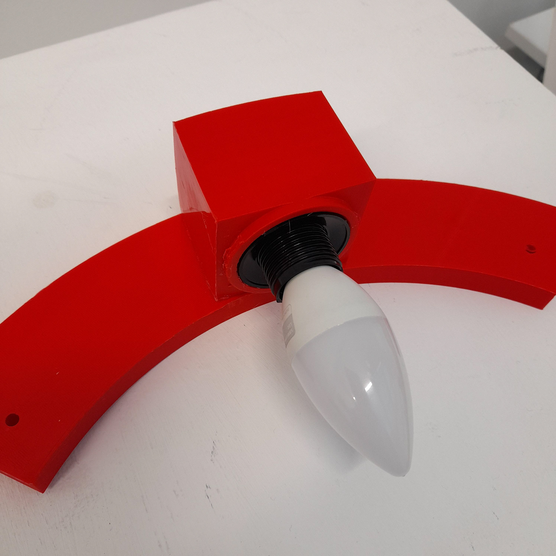
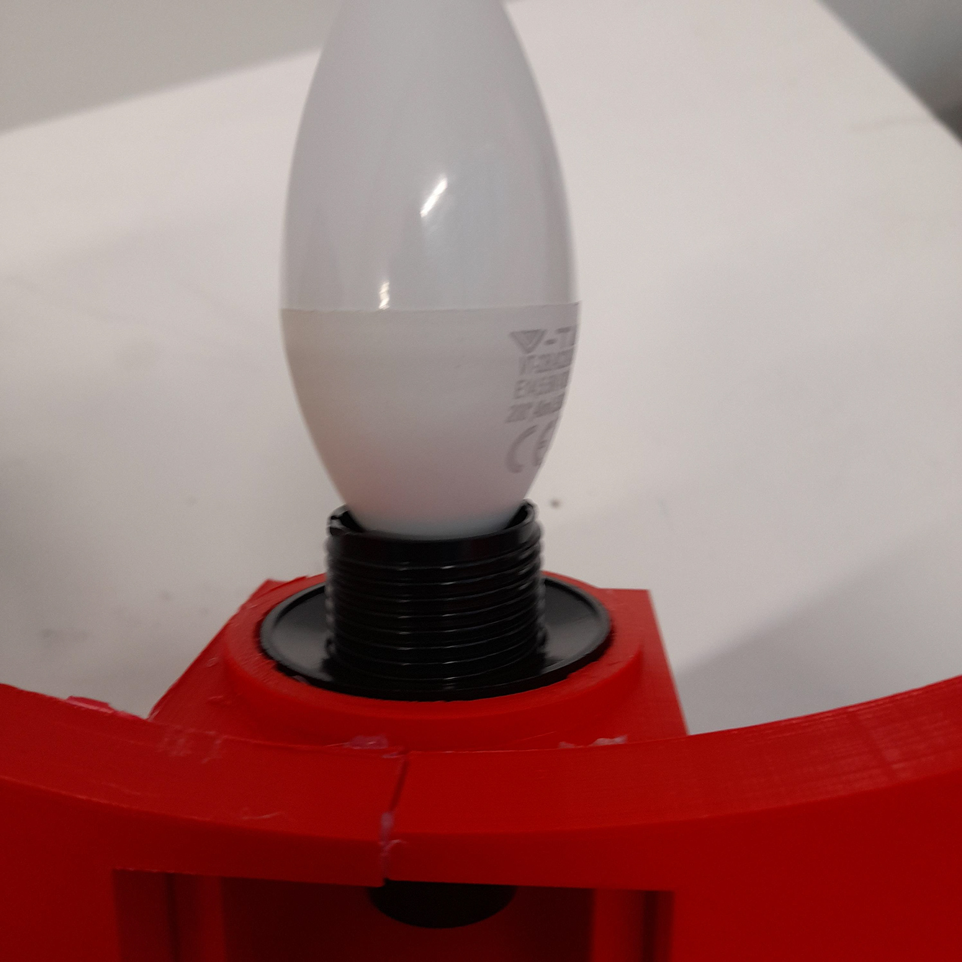
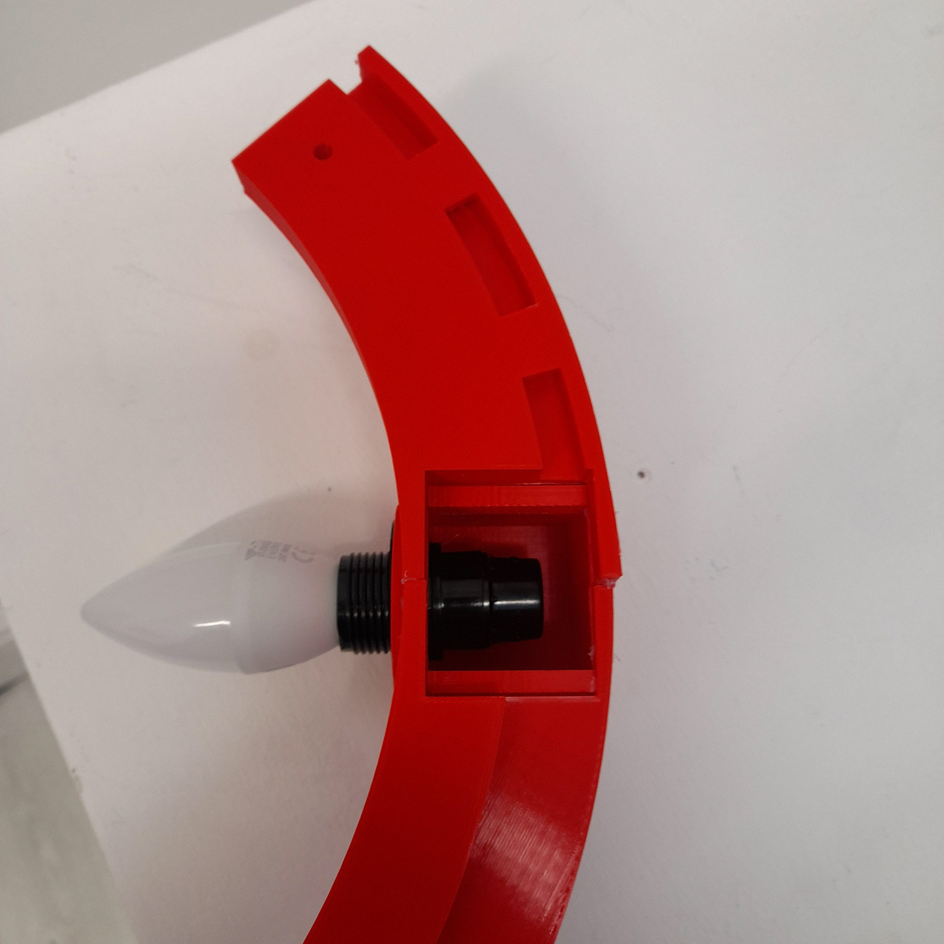
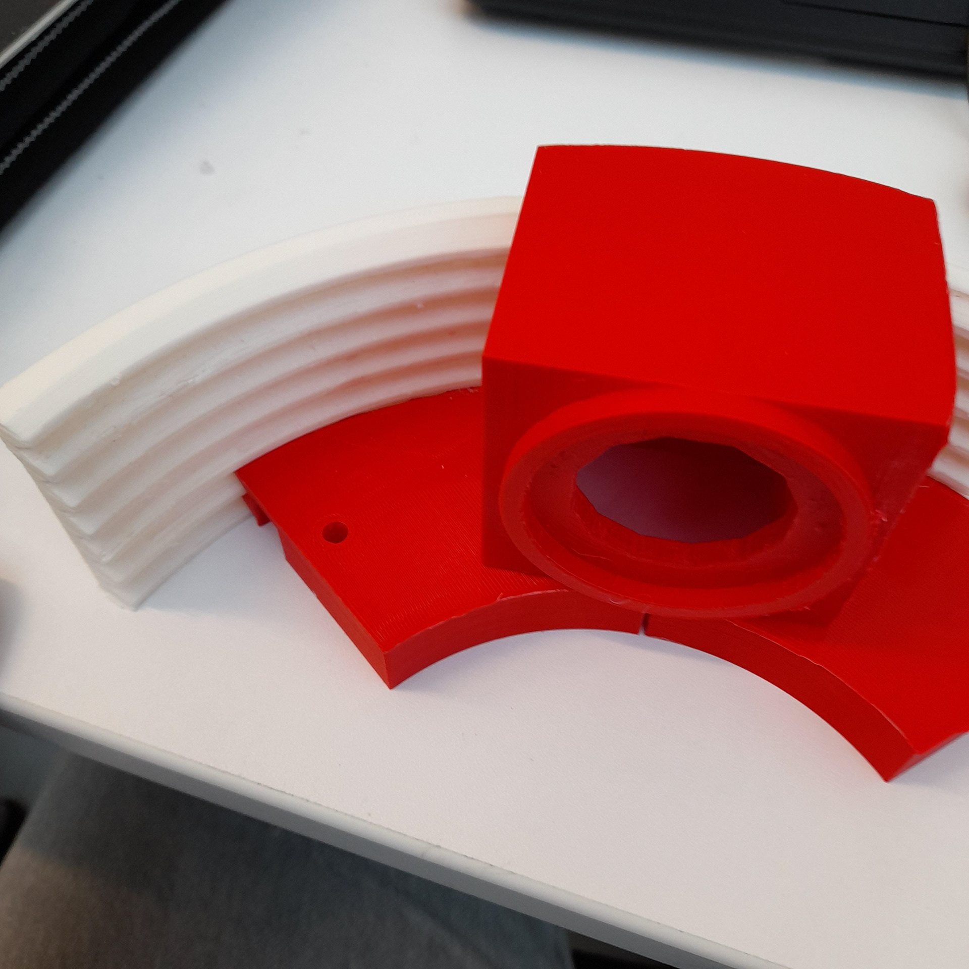
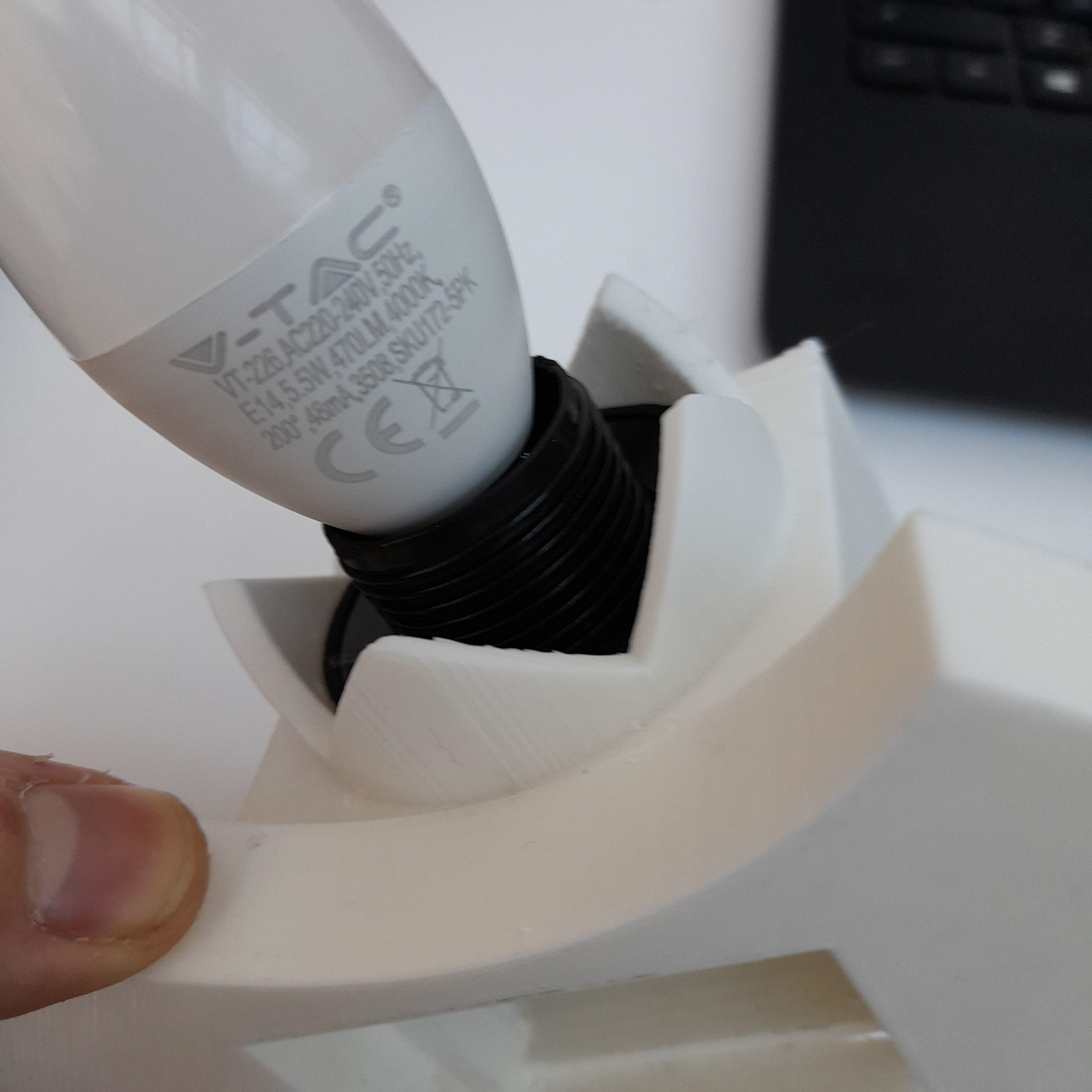
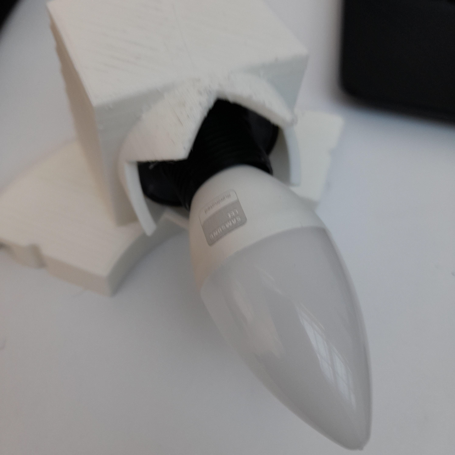
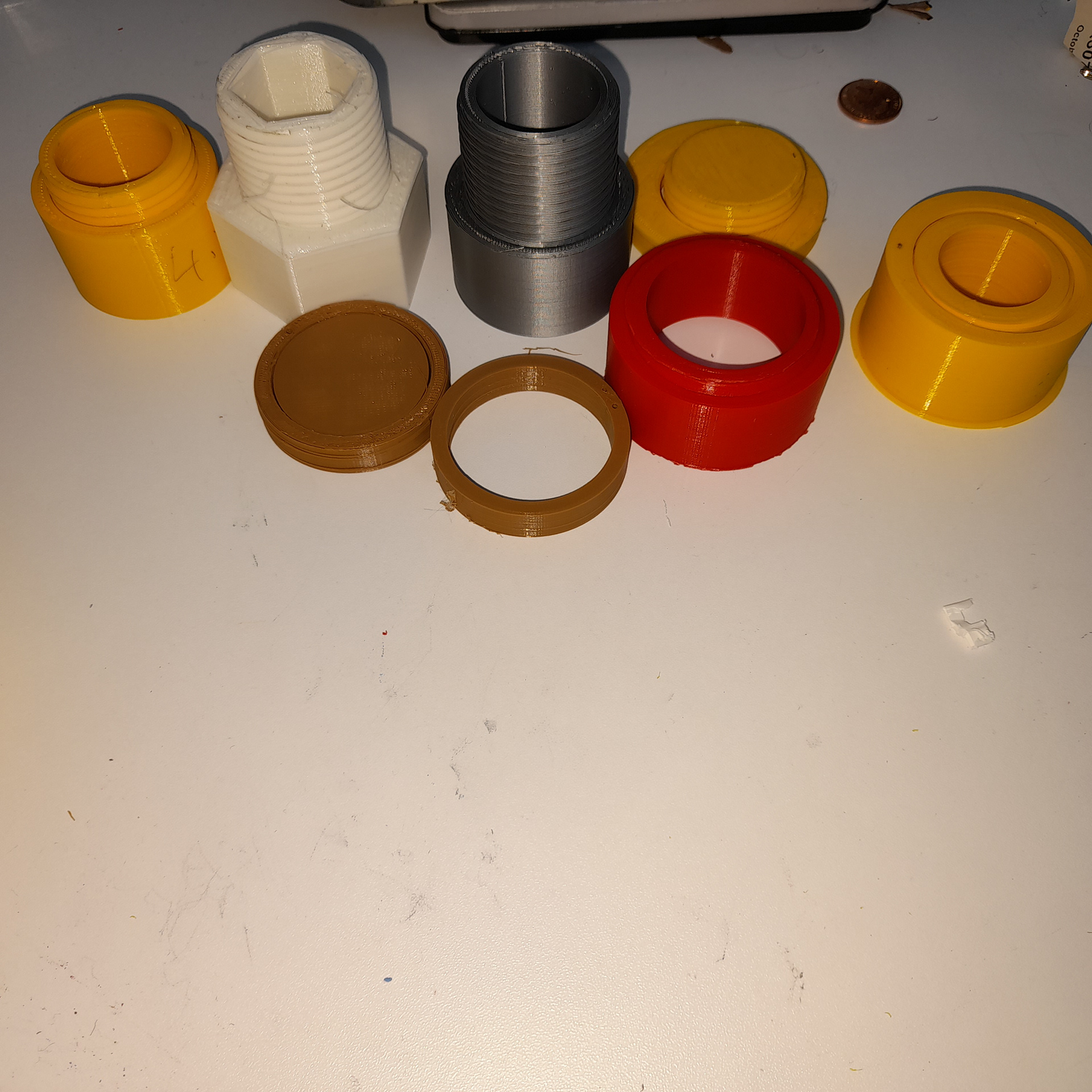
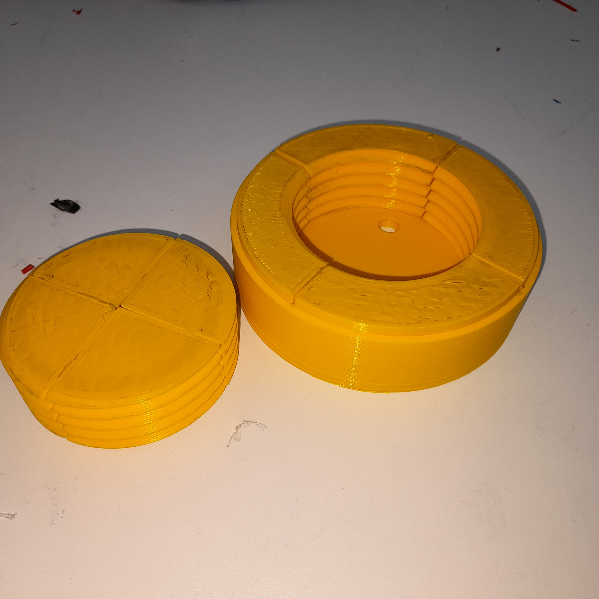
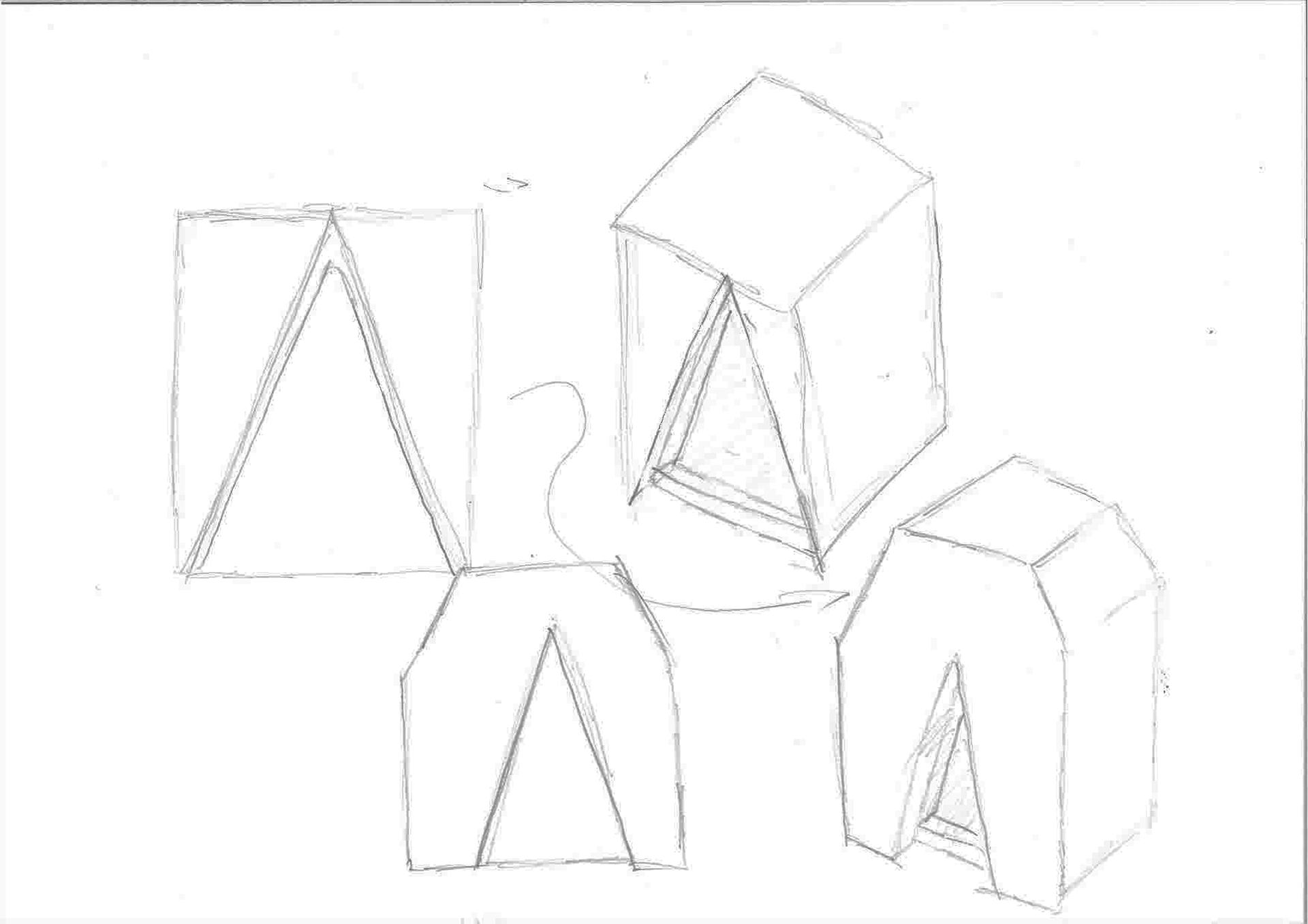
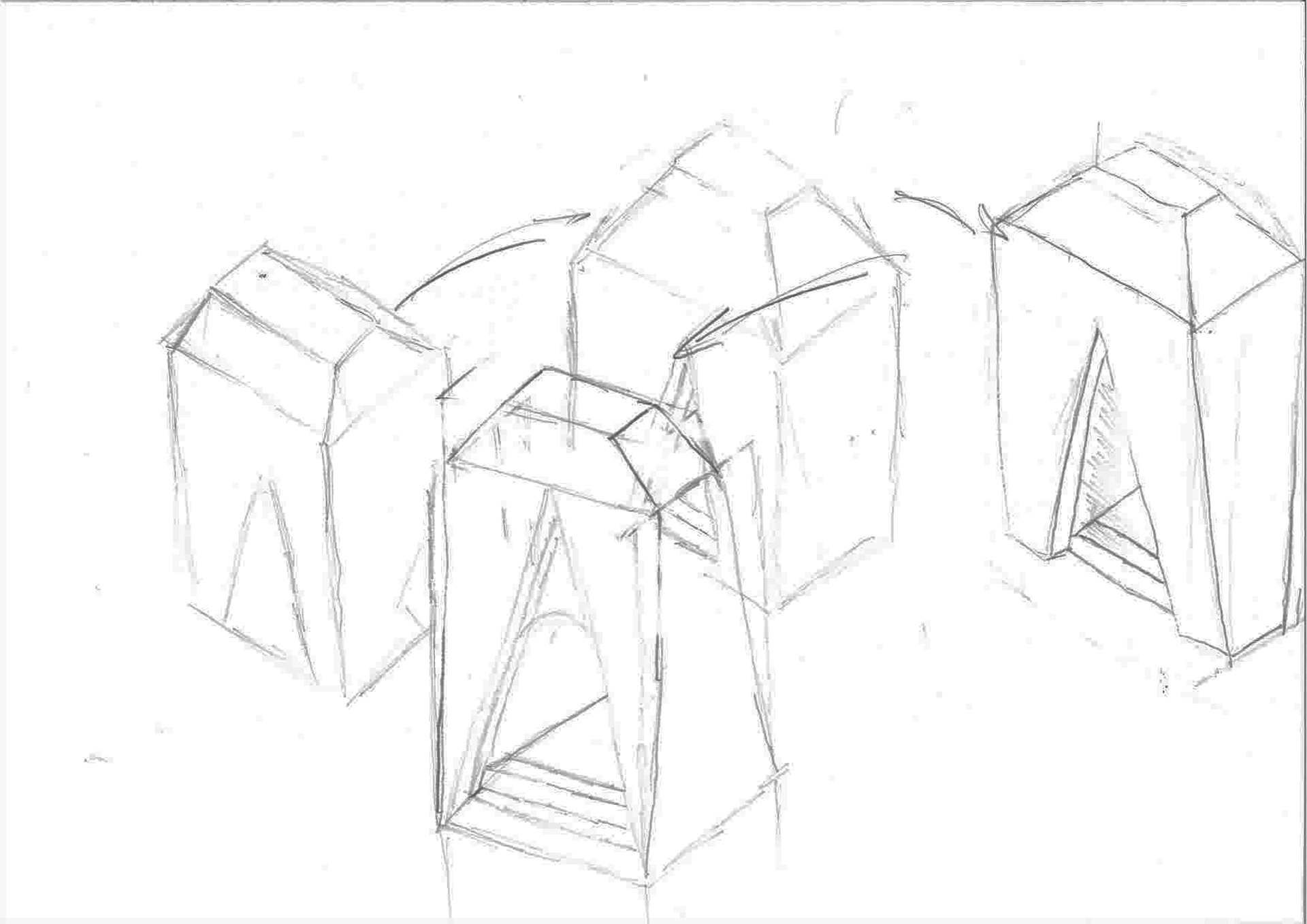
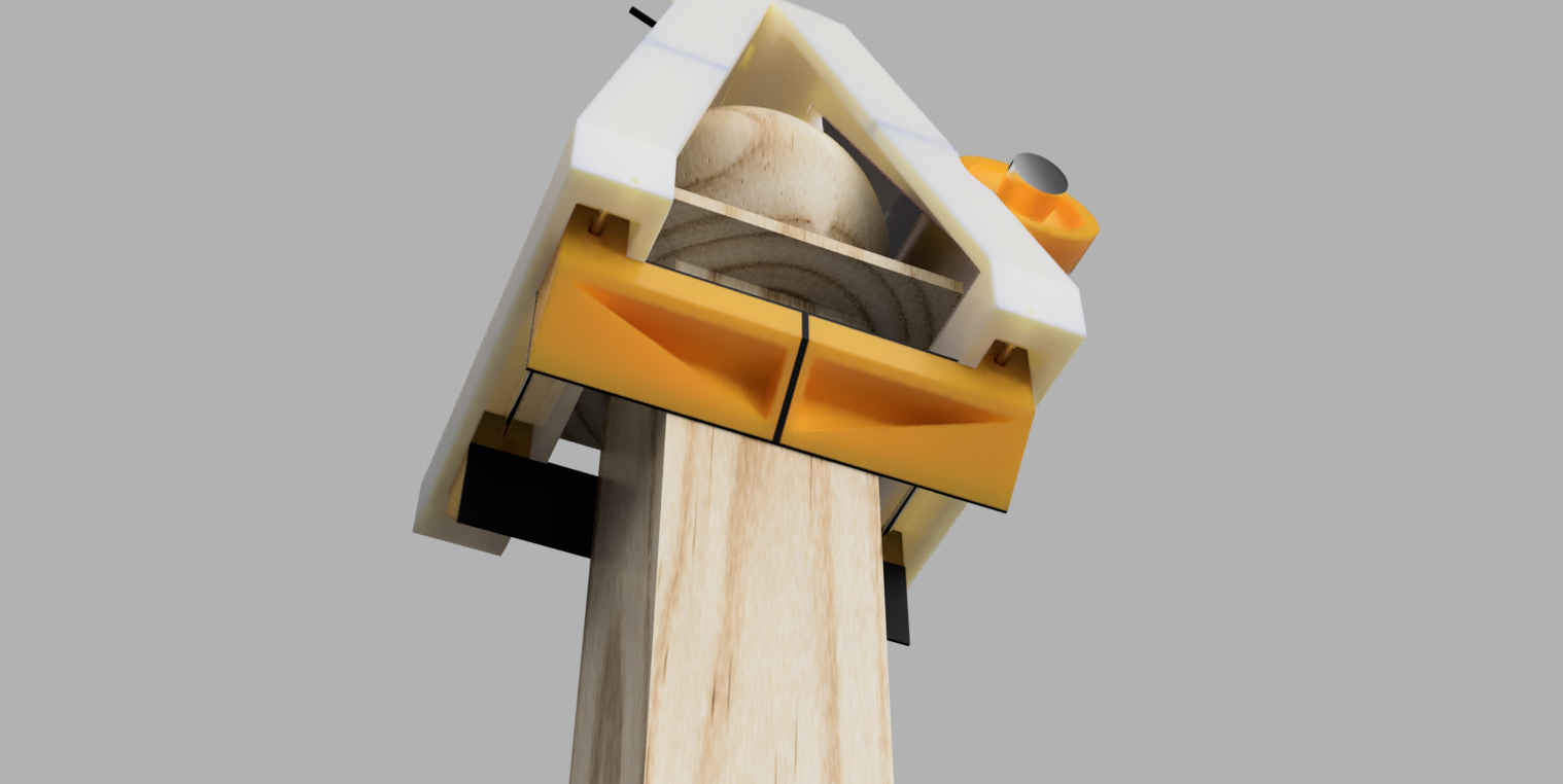
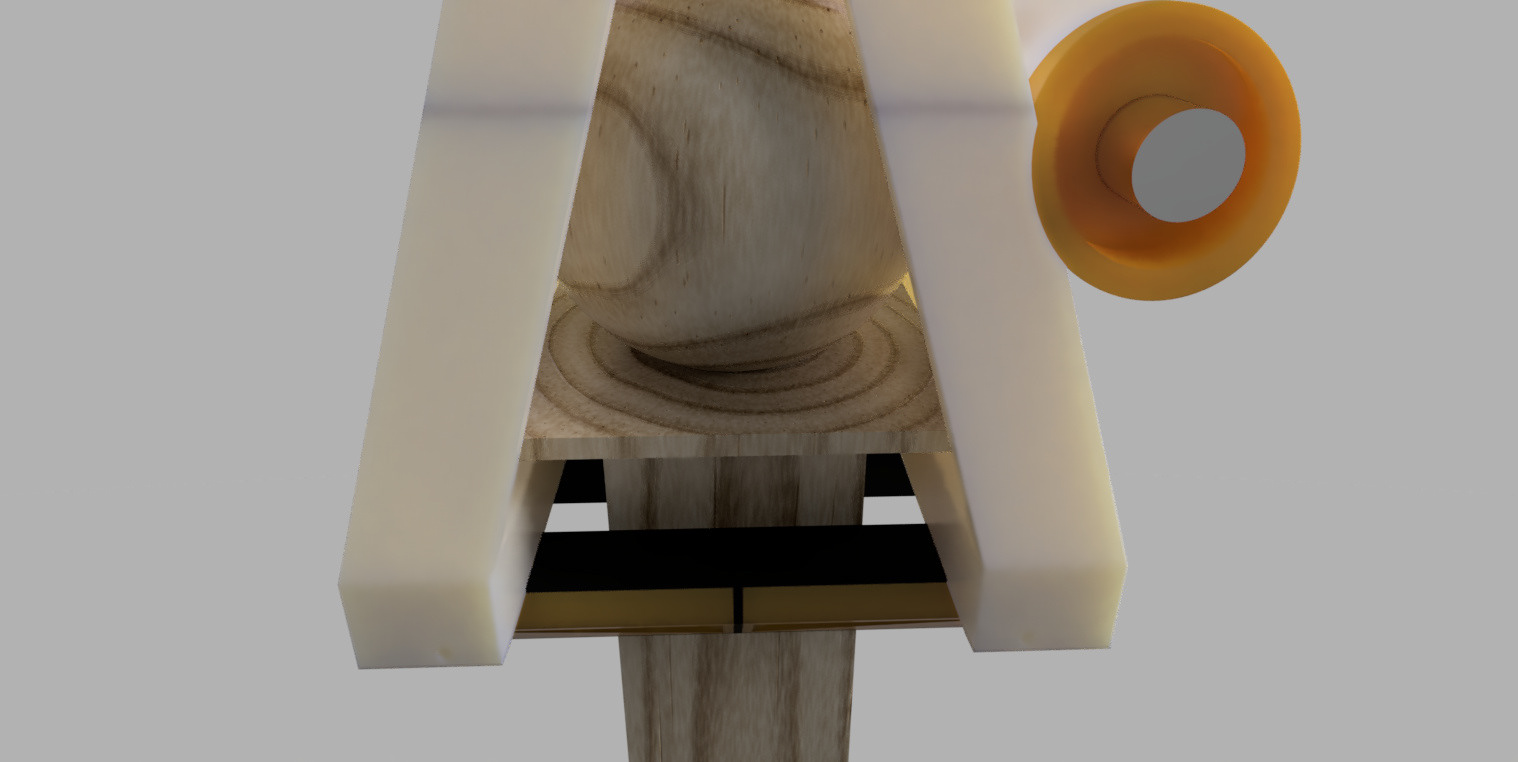
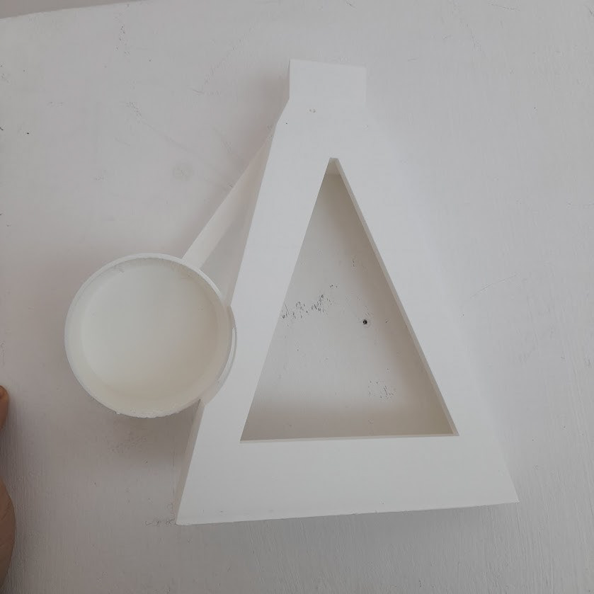
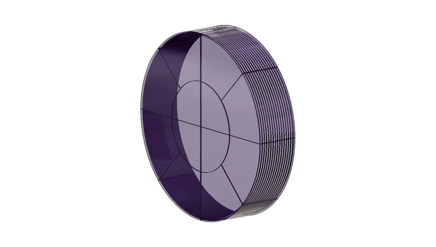
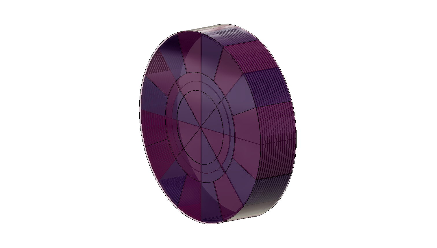
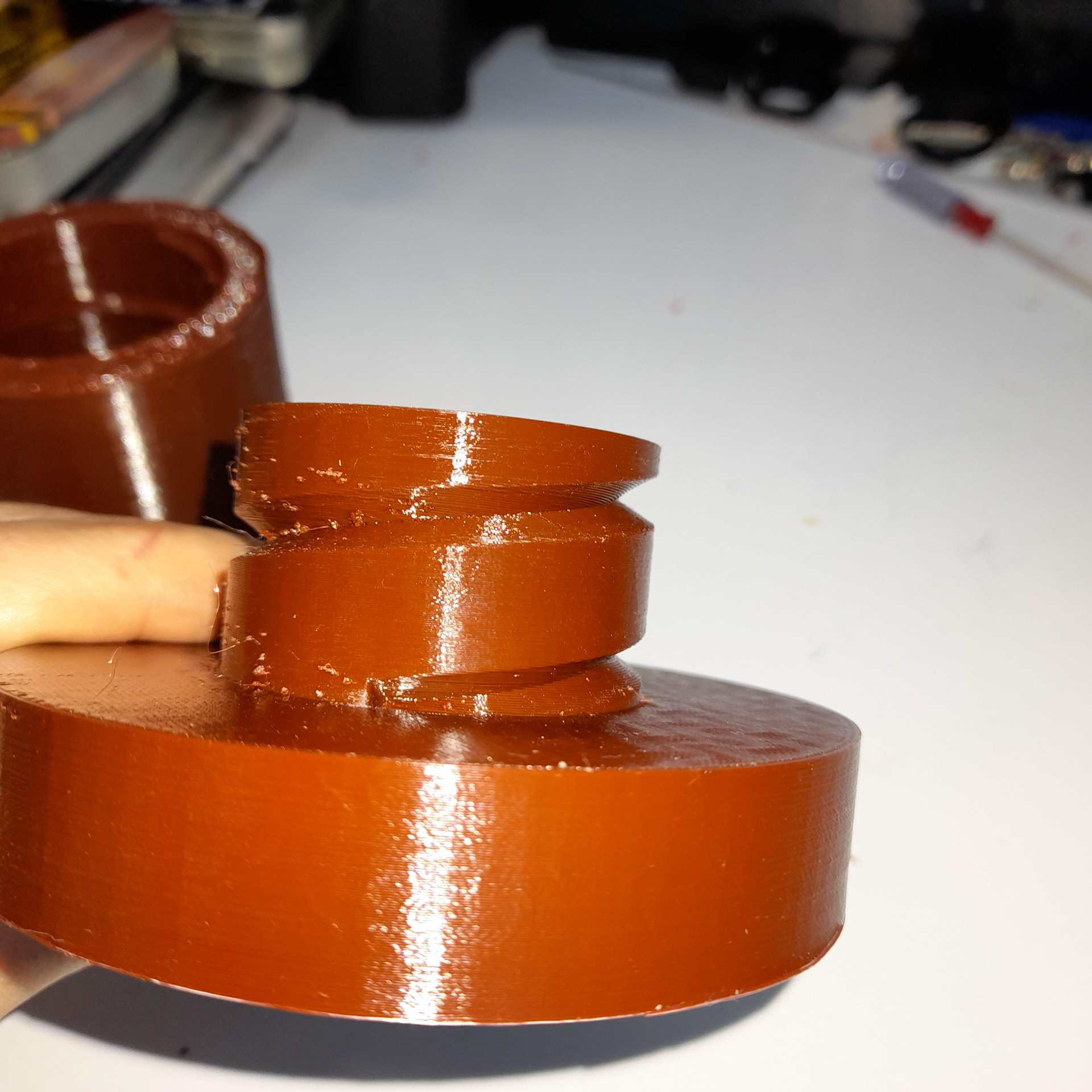
Above is another part model of the bulb holder. This time around the dimensions were more accurate. That being said I'm going to add a feature that will hide the black plastic. Since this part, doesn't need to be visible. Below is another model of the bulb holder, yet this is to try out the thread feature. The idea is that the casing which will protect the bulbs and reduce the glare will be twisted on. Like a water bottle lid. However, I'm going to need to position it differently on the Cura software since there were too many supports which made the model lose its shape while removing them.
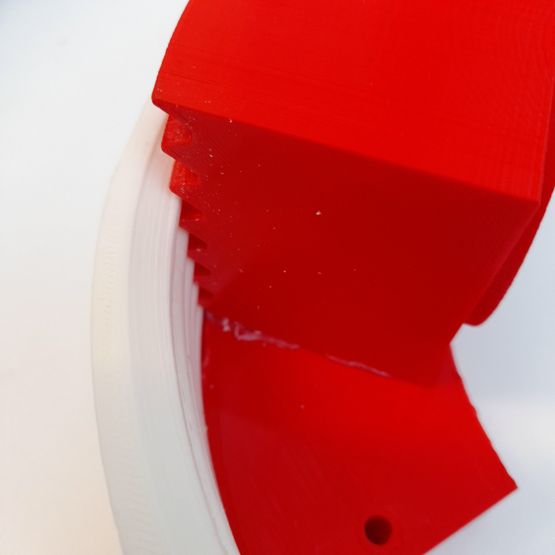
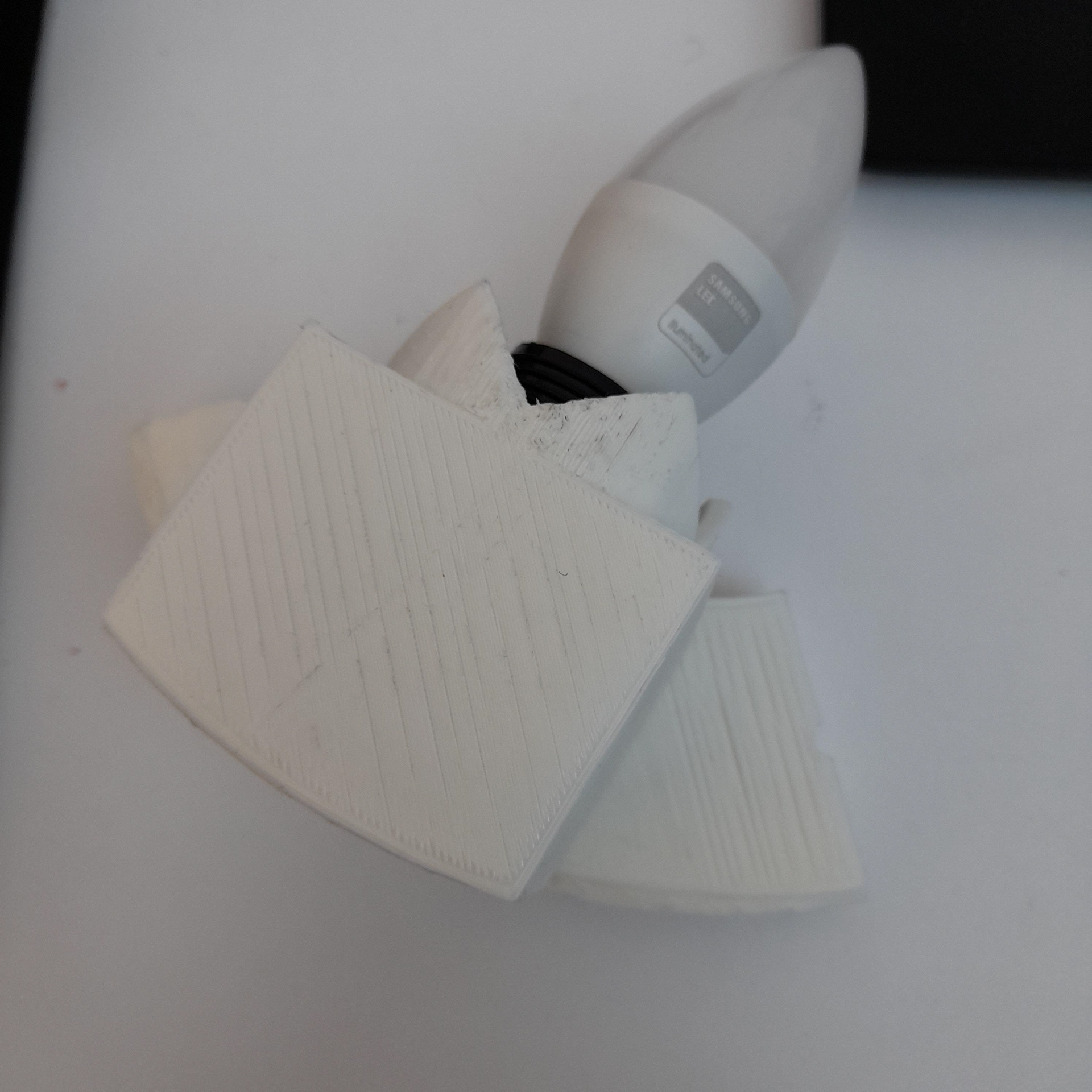
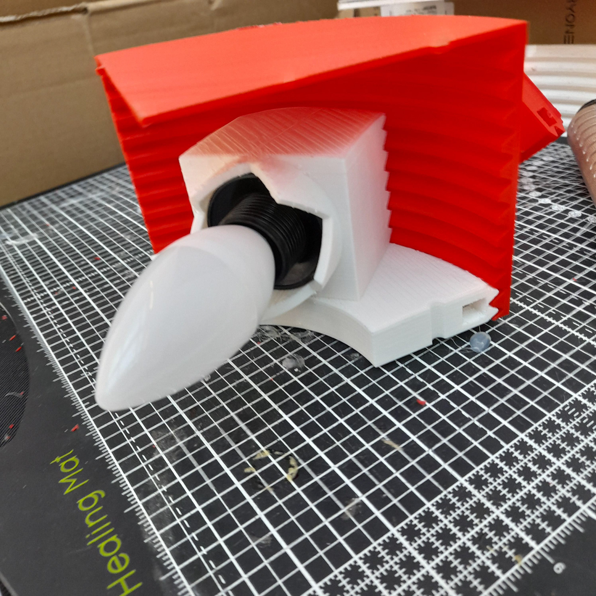
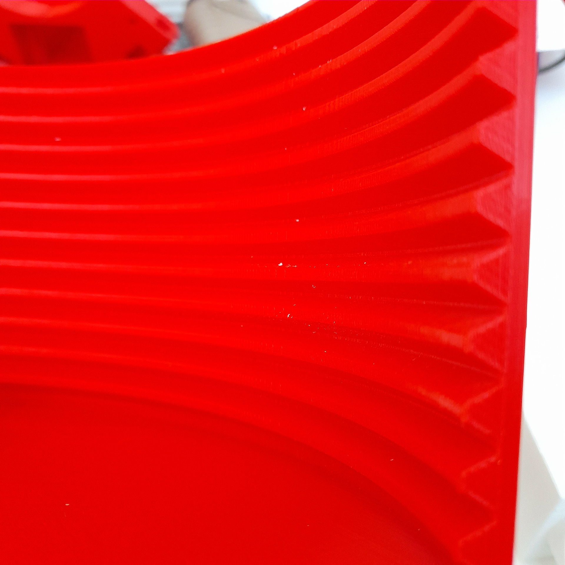
The video above shows how after I had been trying to 3d print different swirl parts, I had managed to get two pieces to work as so. This was done so when it comes to printing the shade for the bulbs I won't waste that material as the red is cheaper.
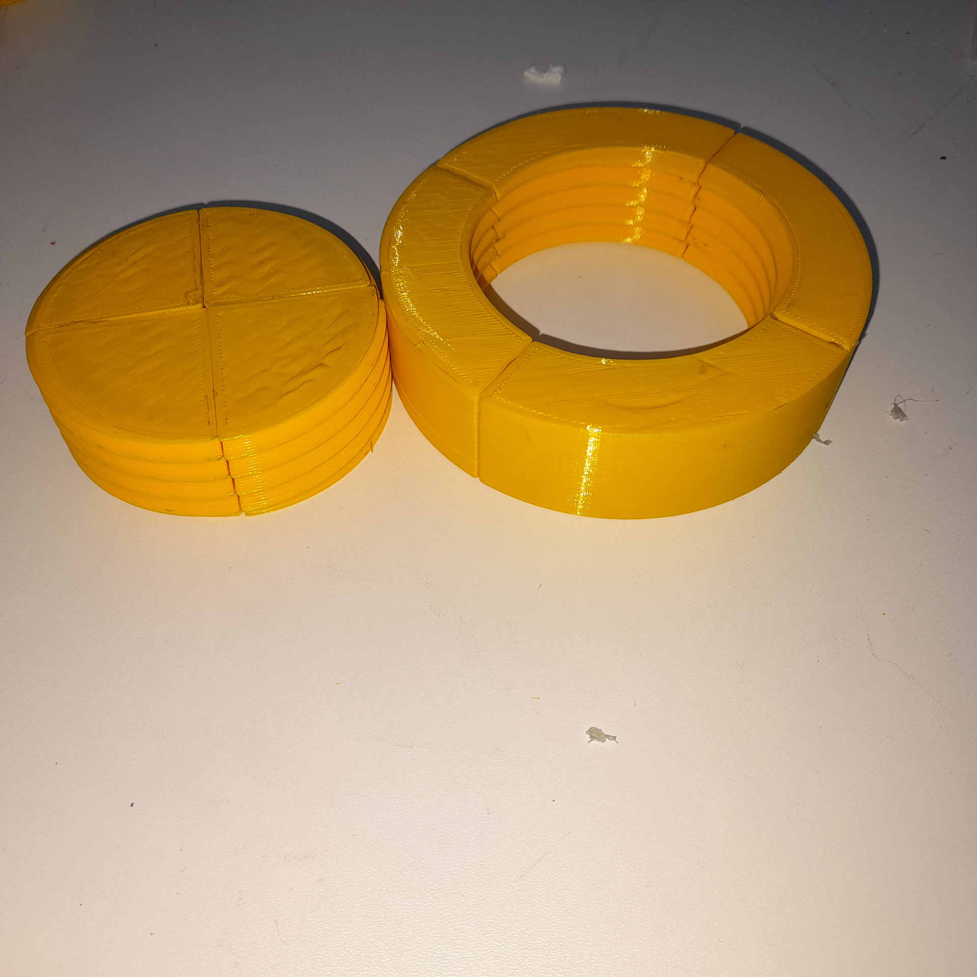
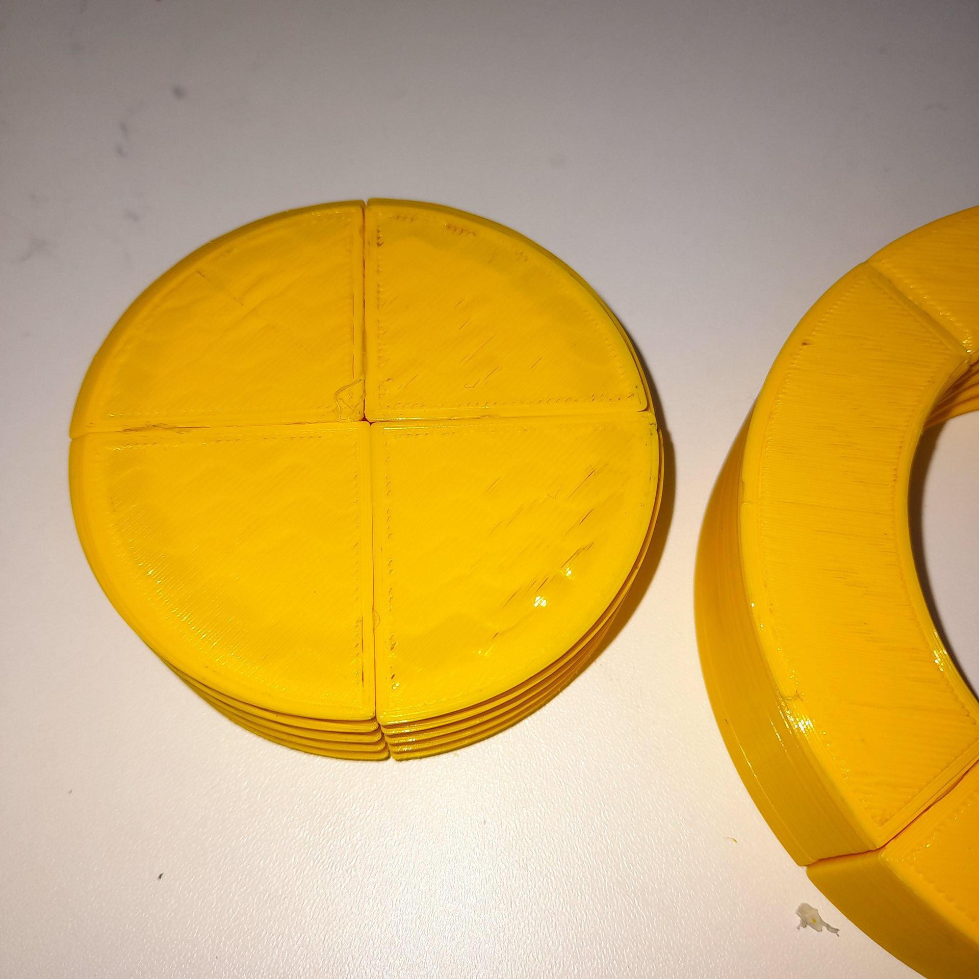
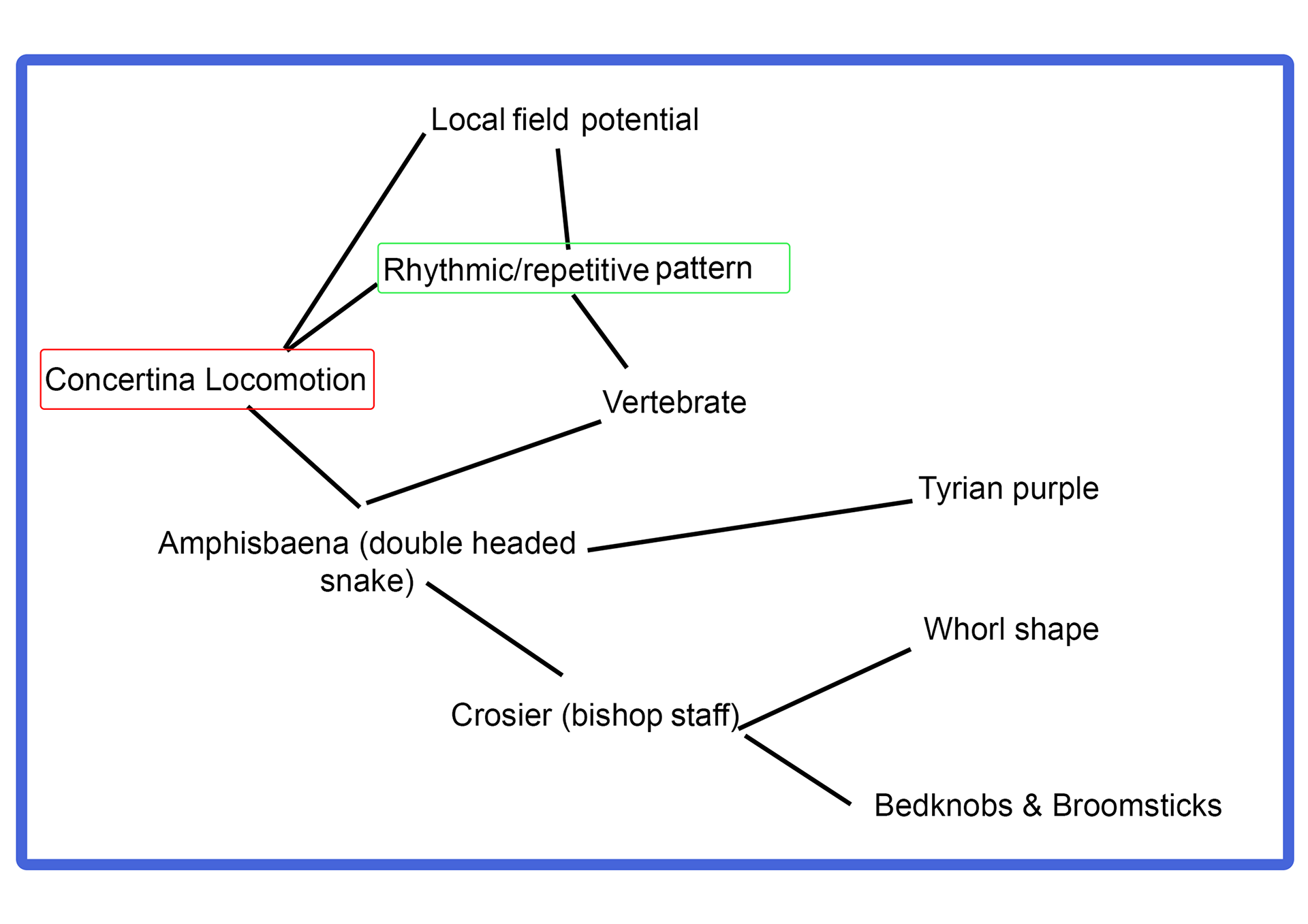
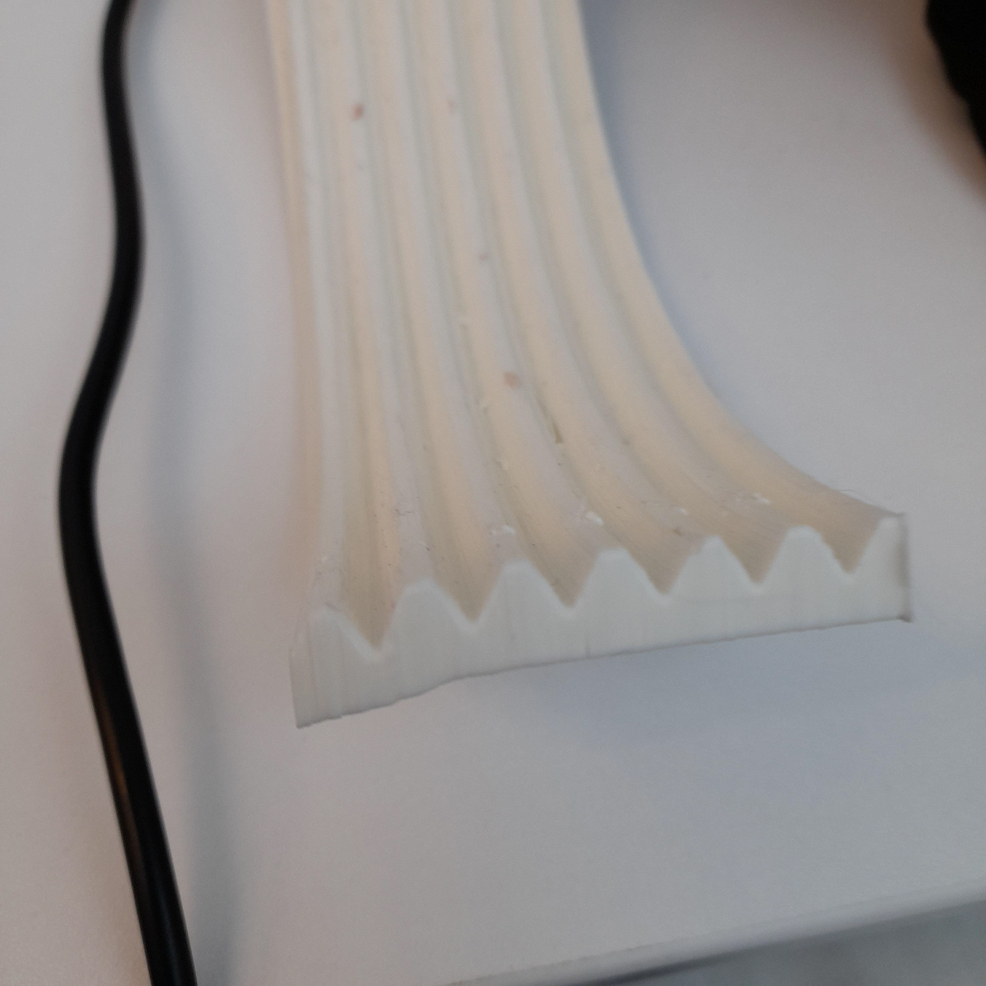
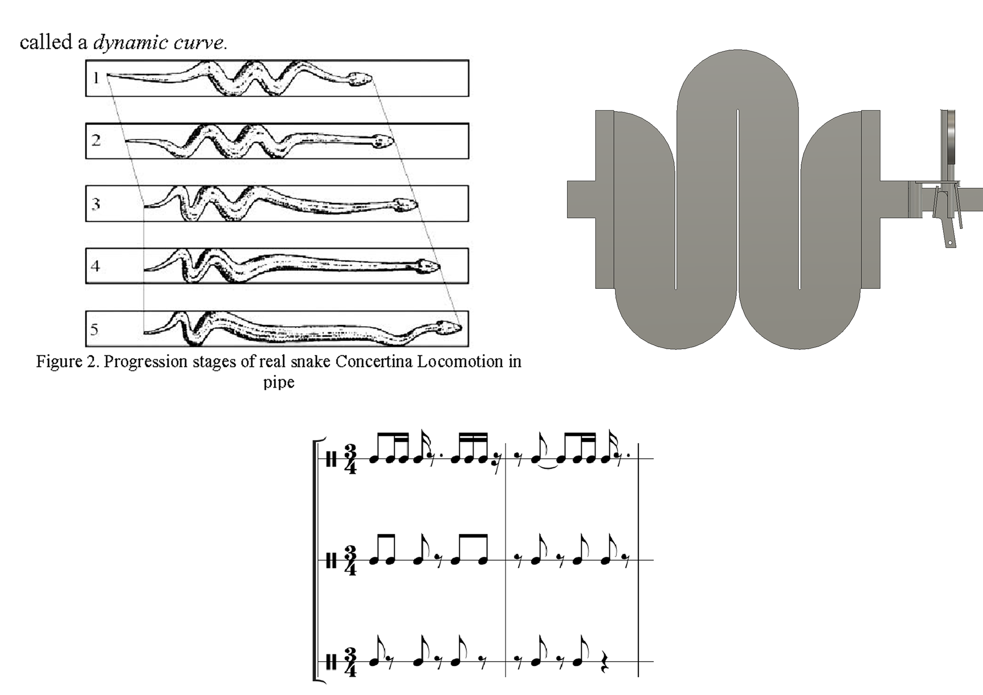
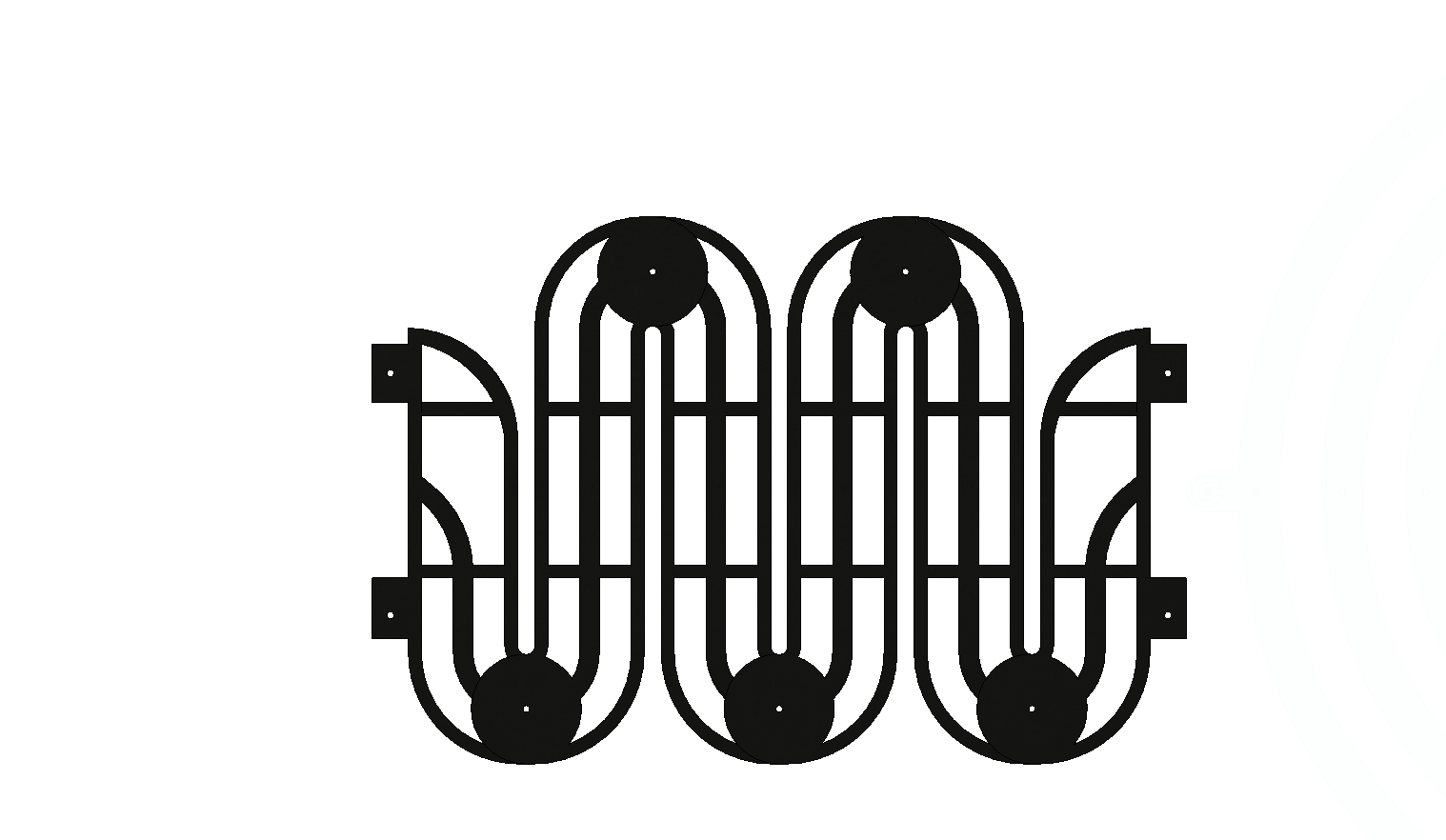
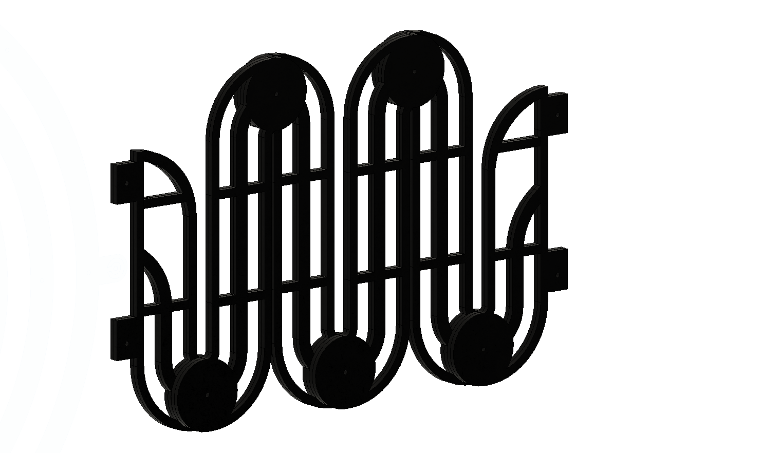
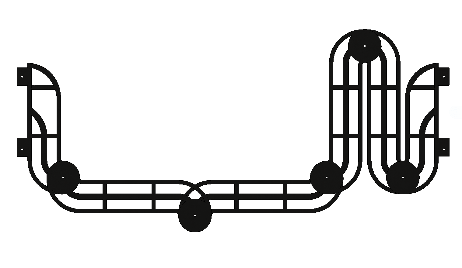
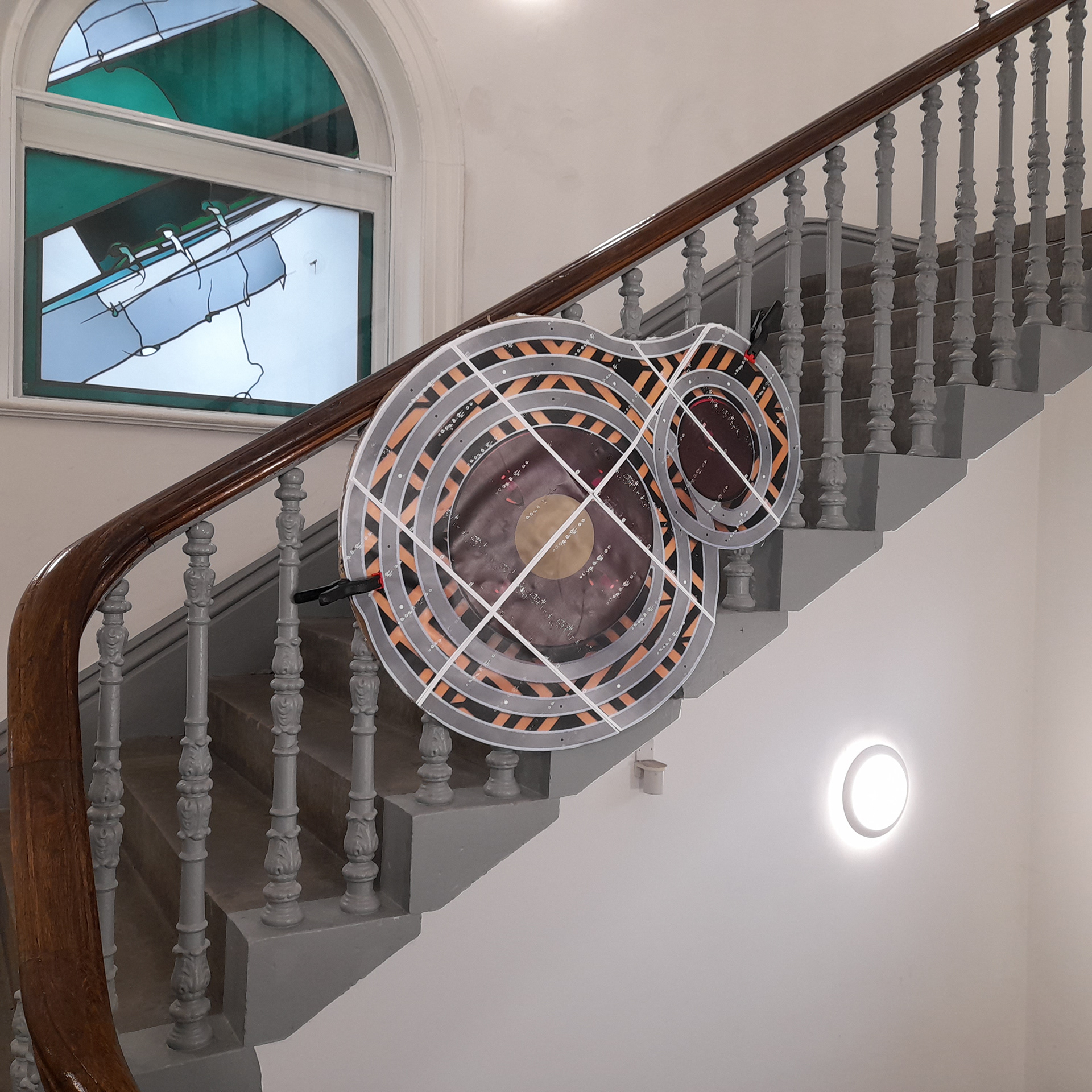
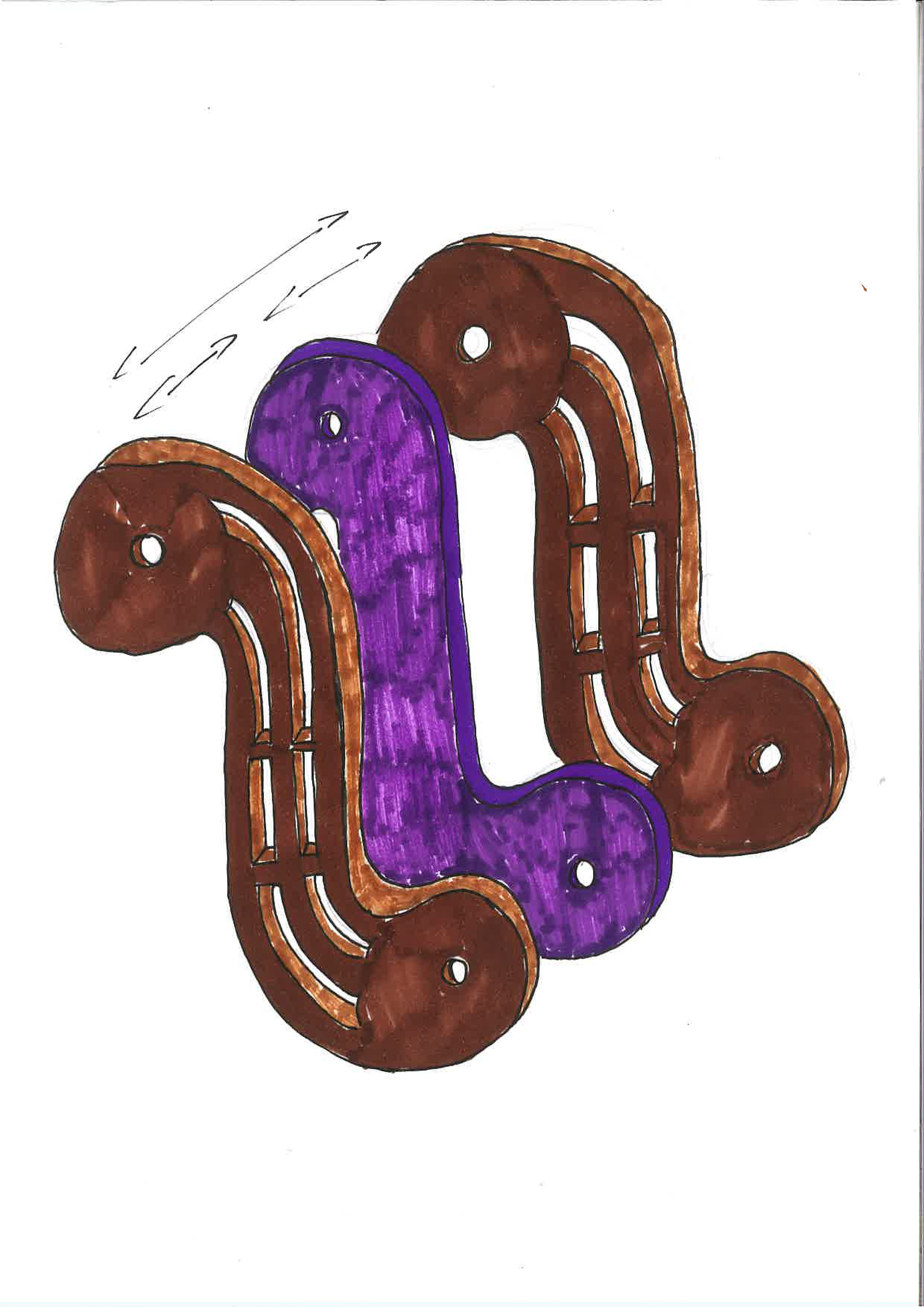
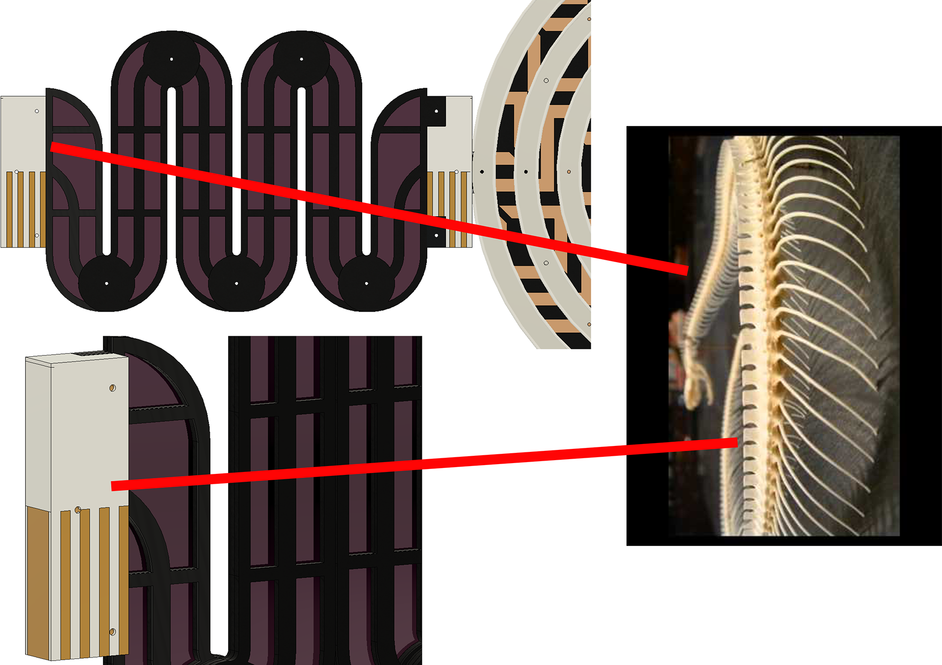
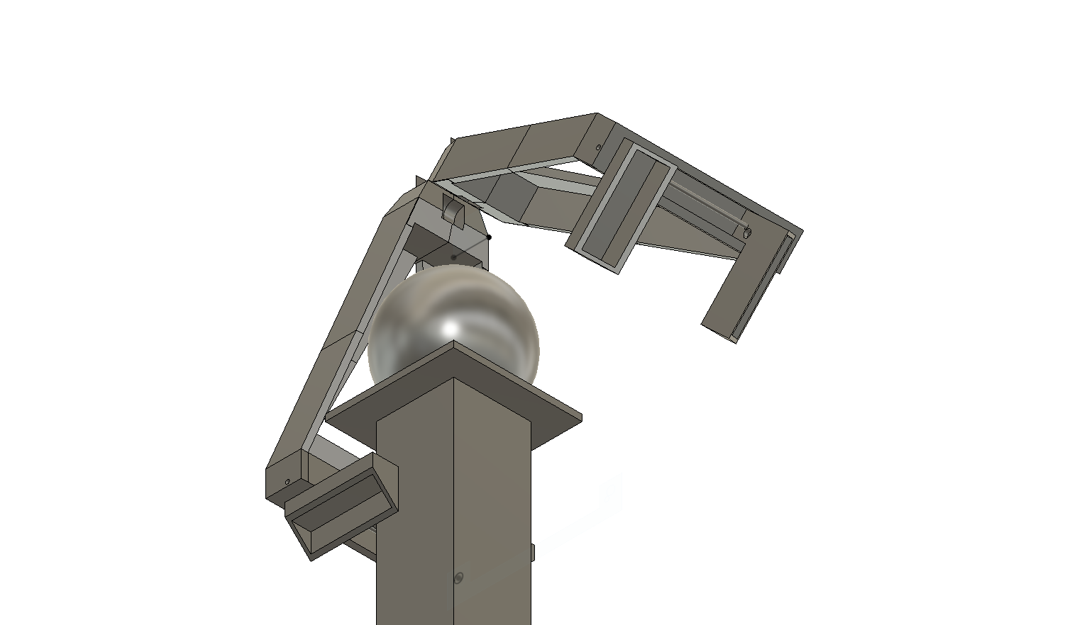
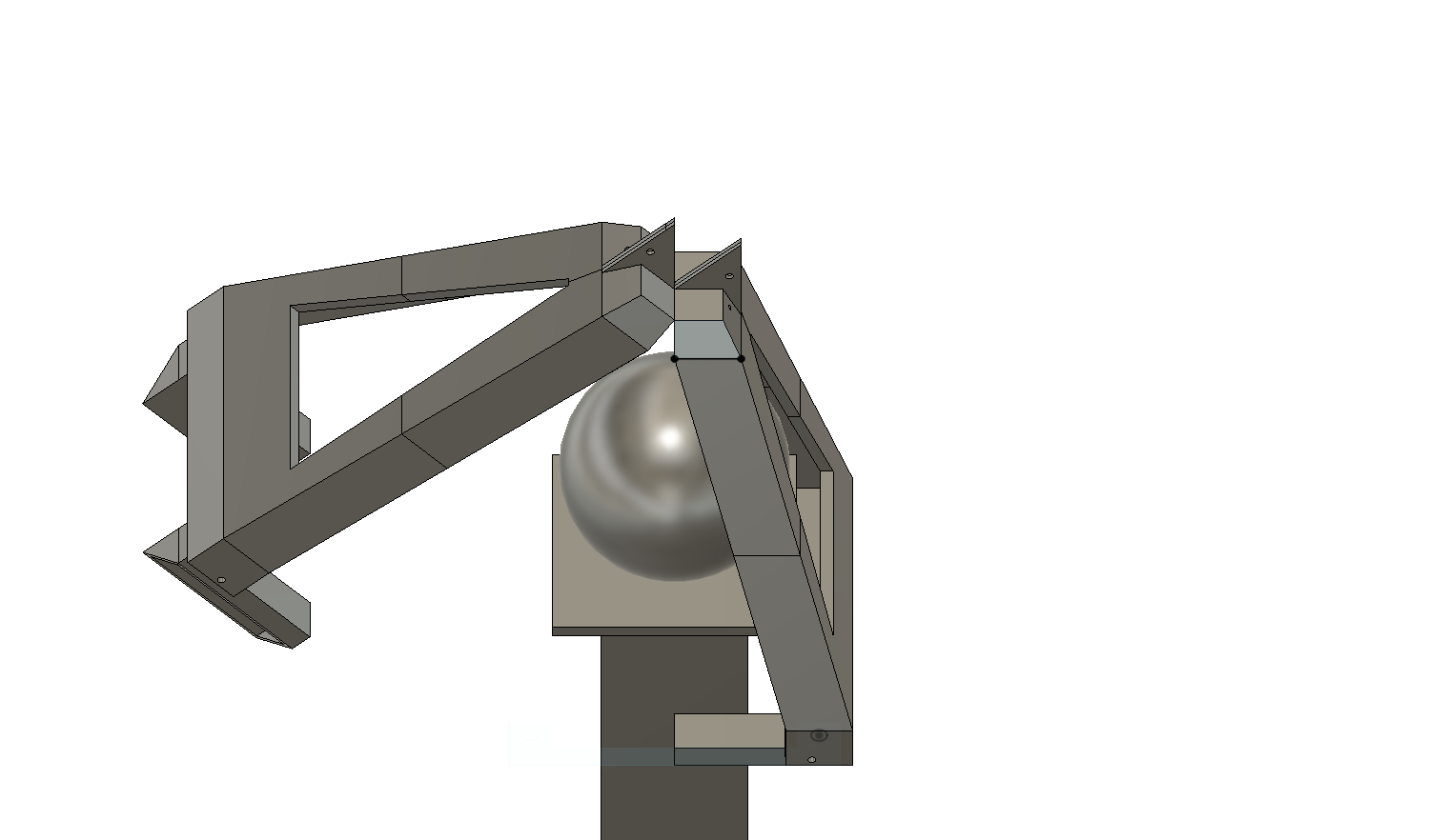
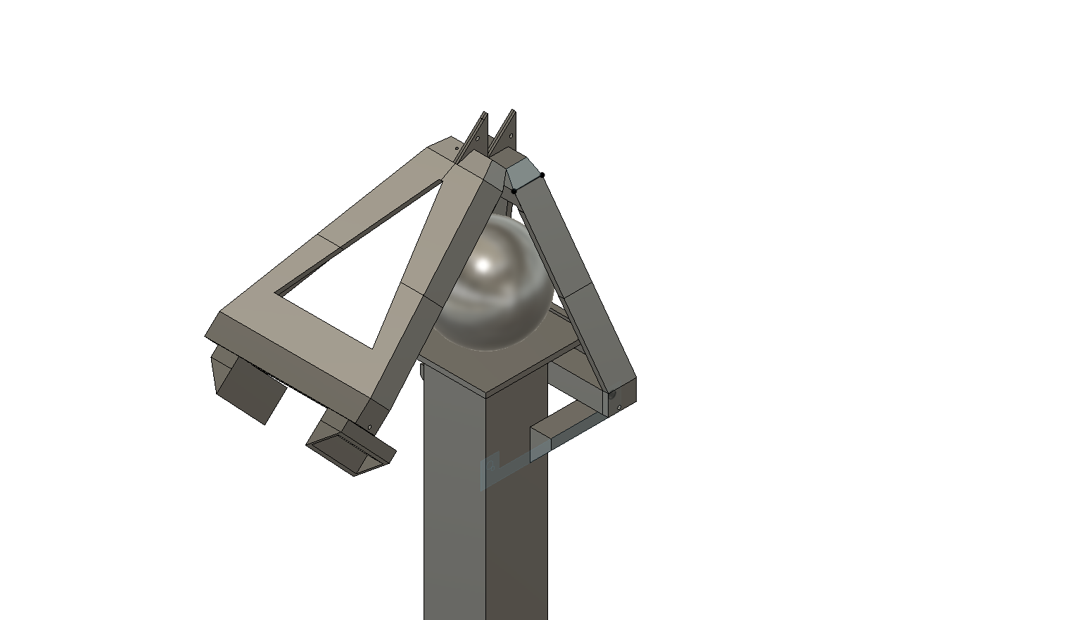
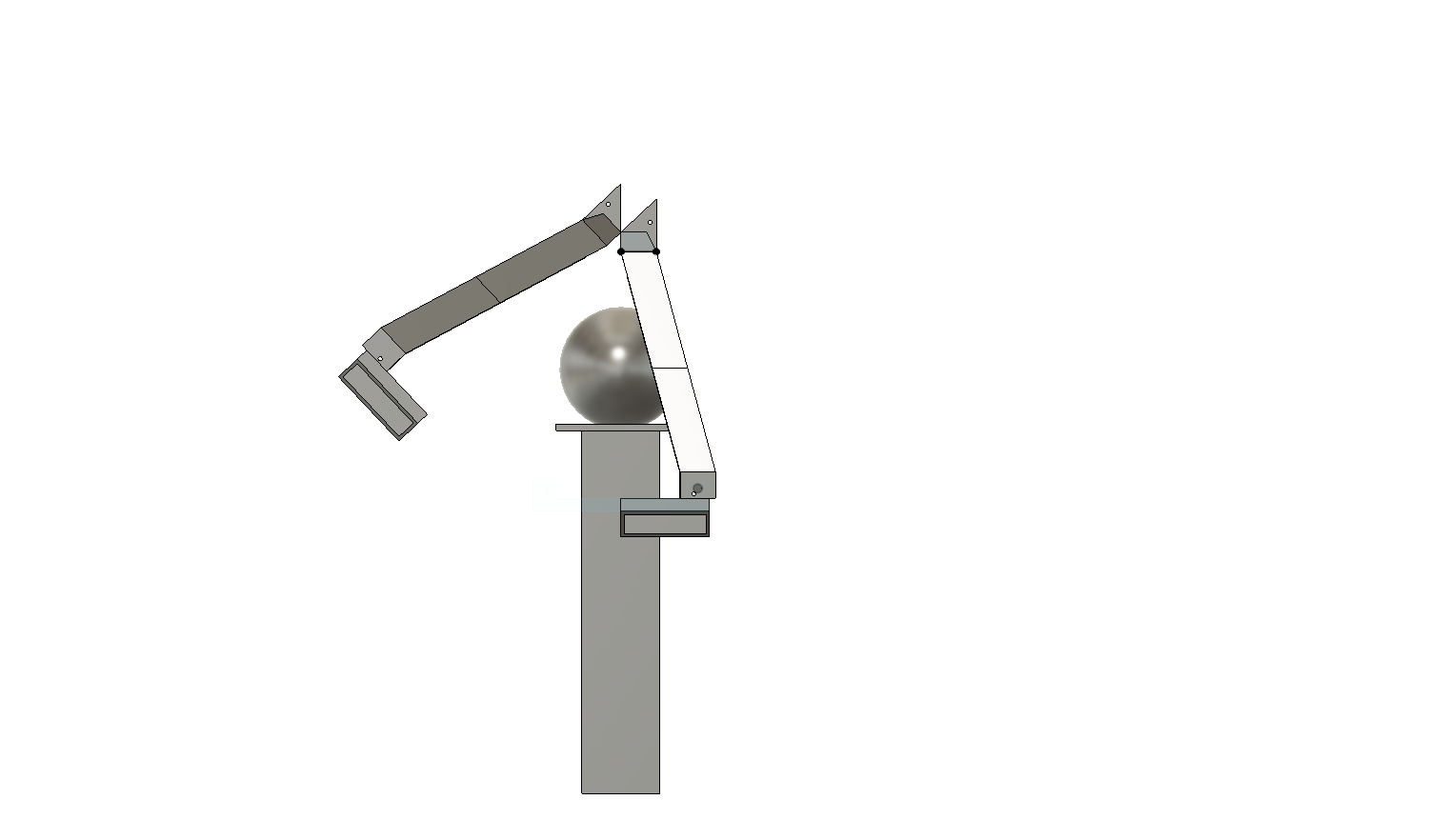
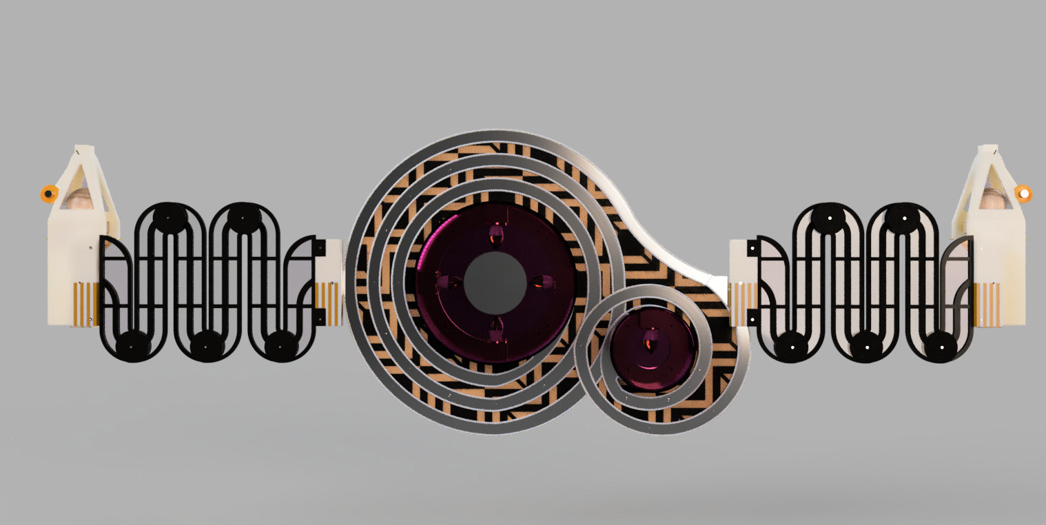
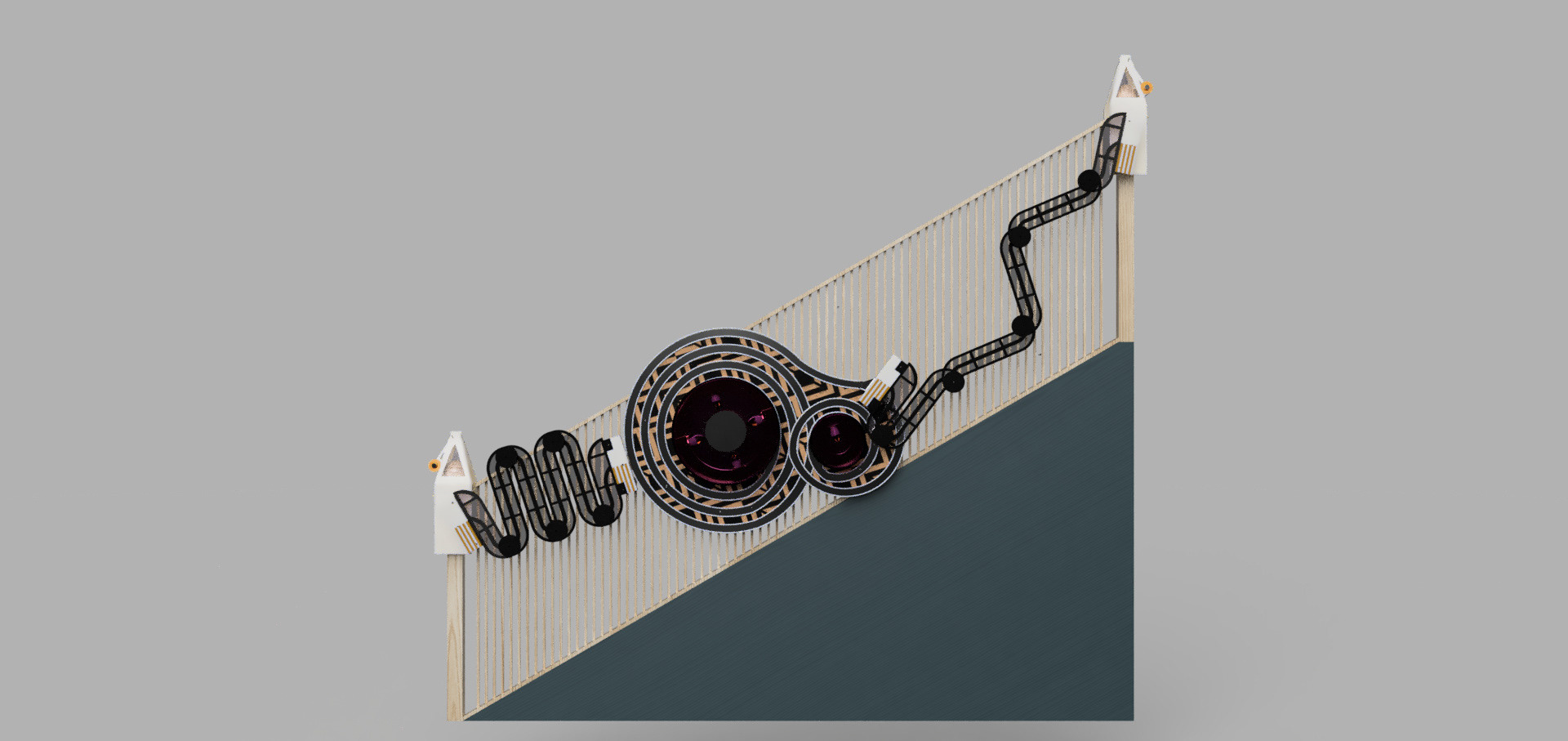
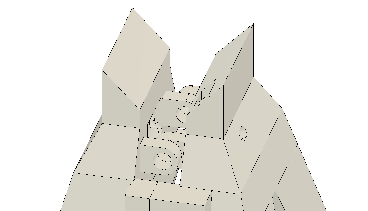
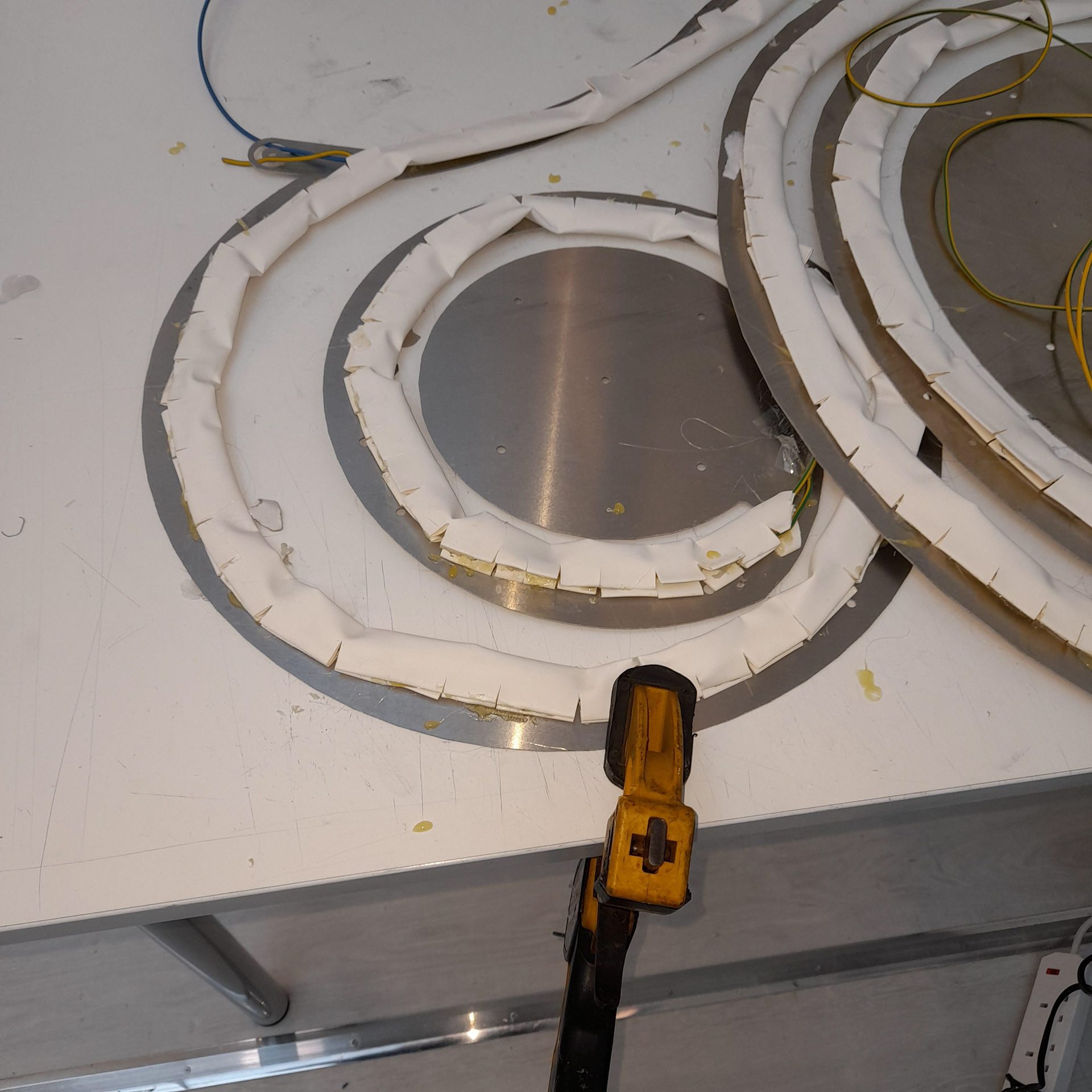
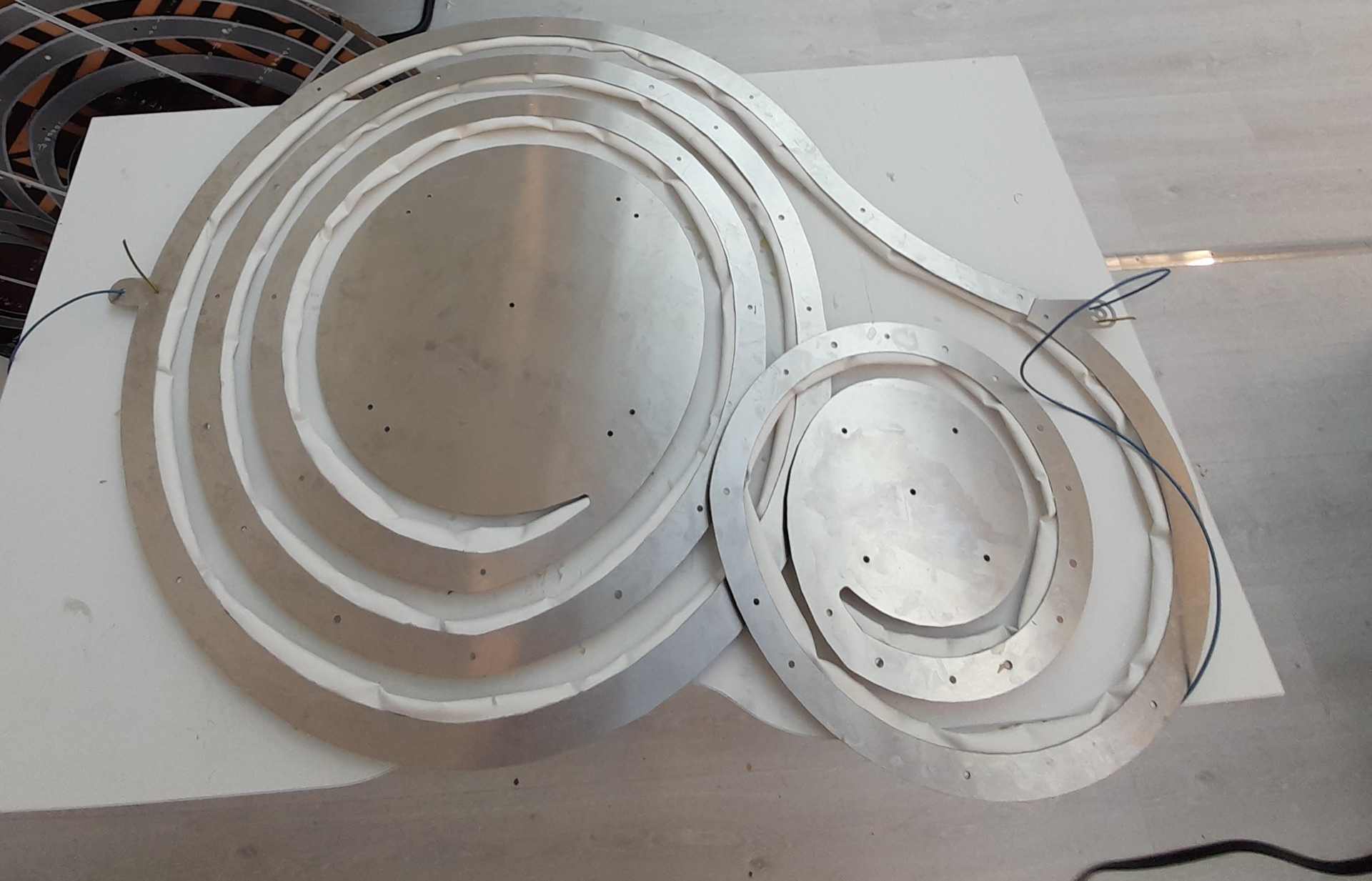
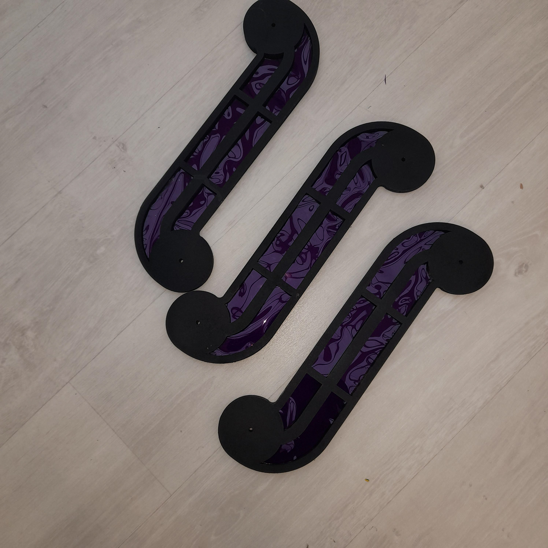
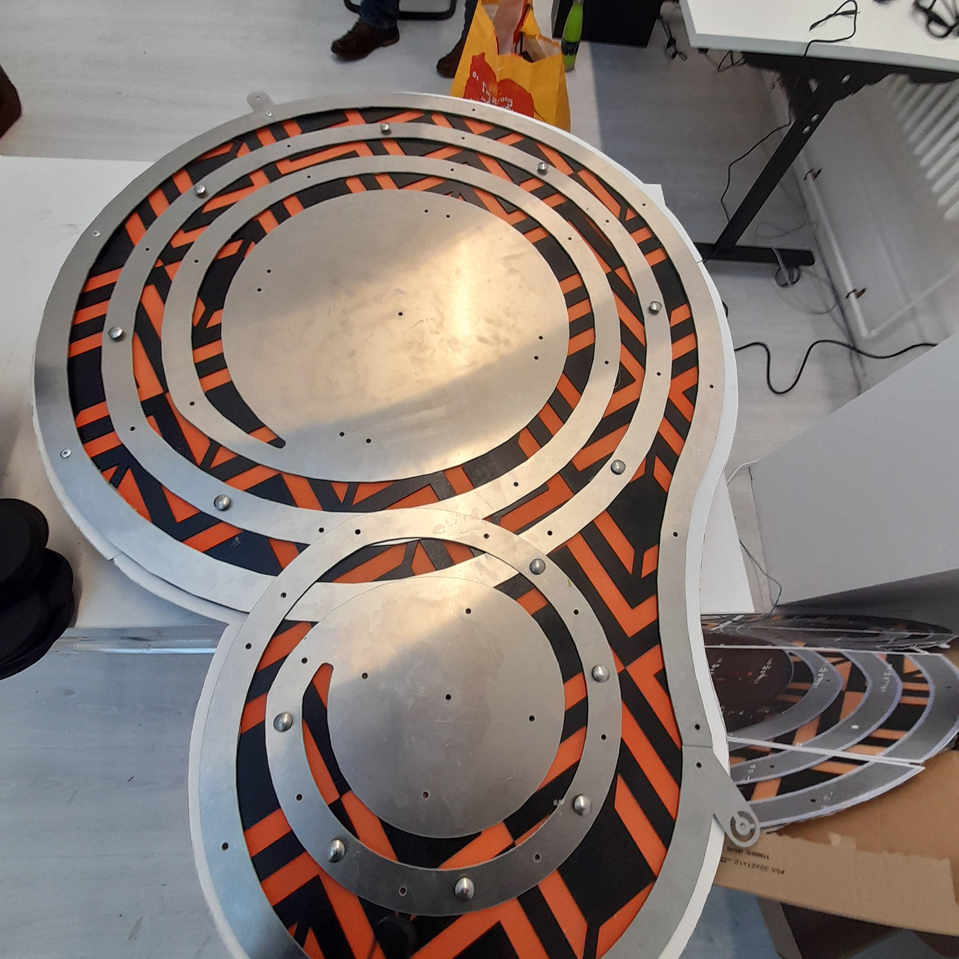
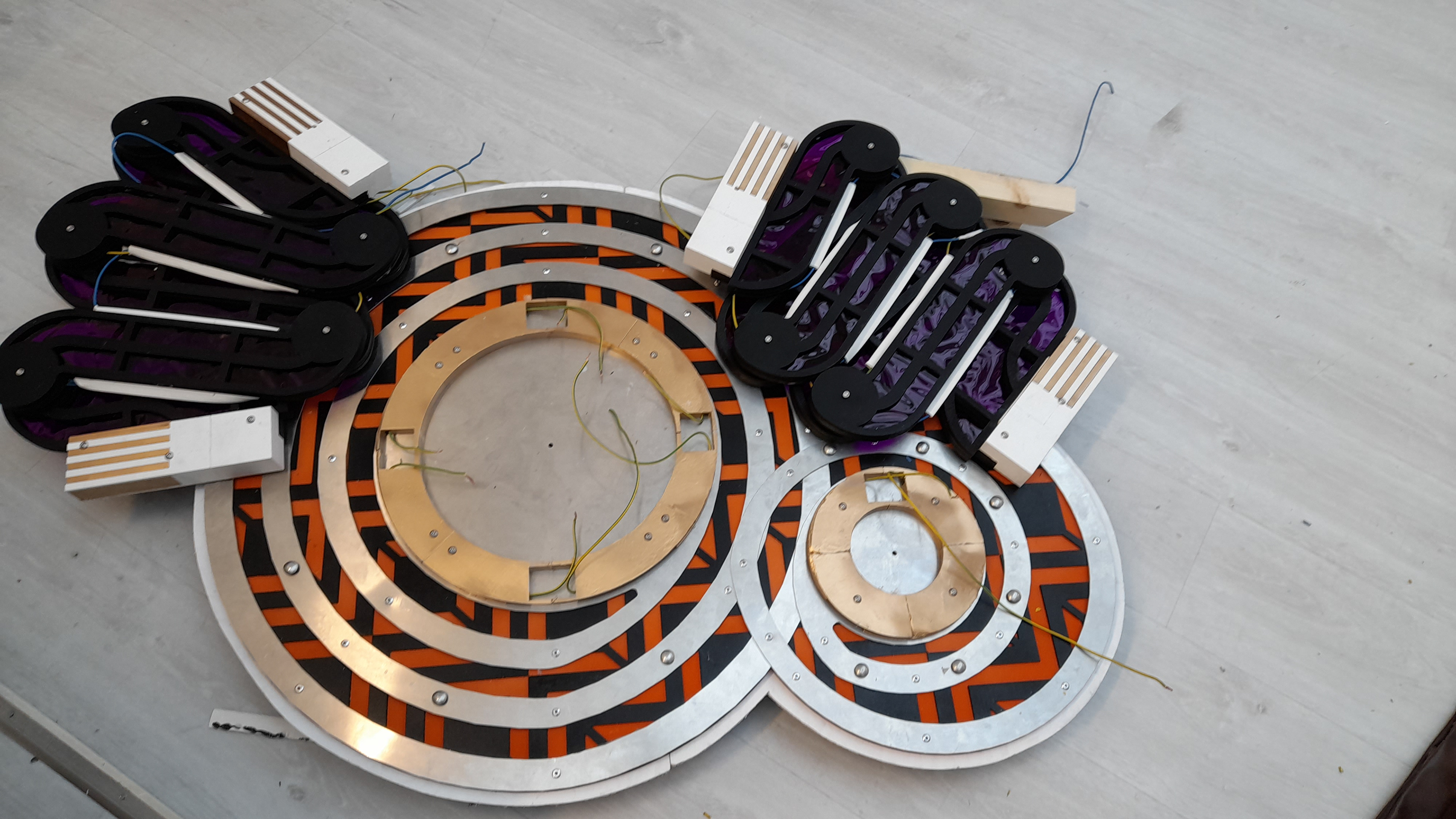
concertina locomotion is how a legless creature moves. Because of the feature on my light that requires movement so it can be attached in different areas on stairs, it needs a part that can move. Also because stairs are not all the same size. My idea for this was to use a combination of the concertina and the rhythmic pattern (Not repetitive this will be shown on another feature later on).
Between each part is a washer which will ease movement. The cable will also have to be attached to these parts, I will show a diagram later on explaining how it will be attached but a thin piece of plywood/balsa will be added on top to hide any glue, drill, marks that are still present after being spray painted.
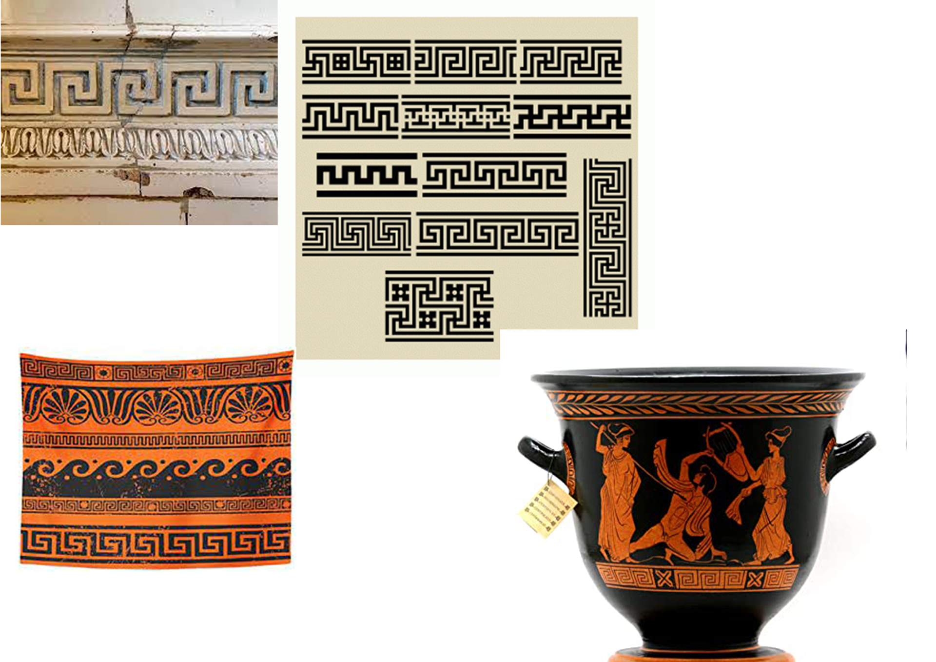
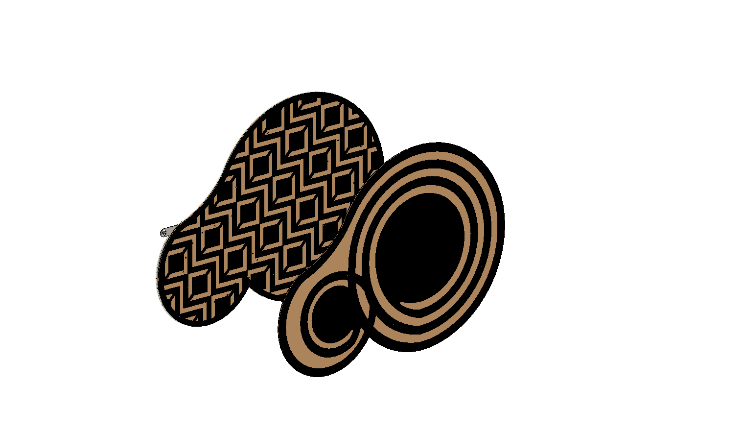
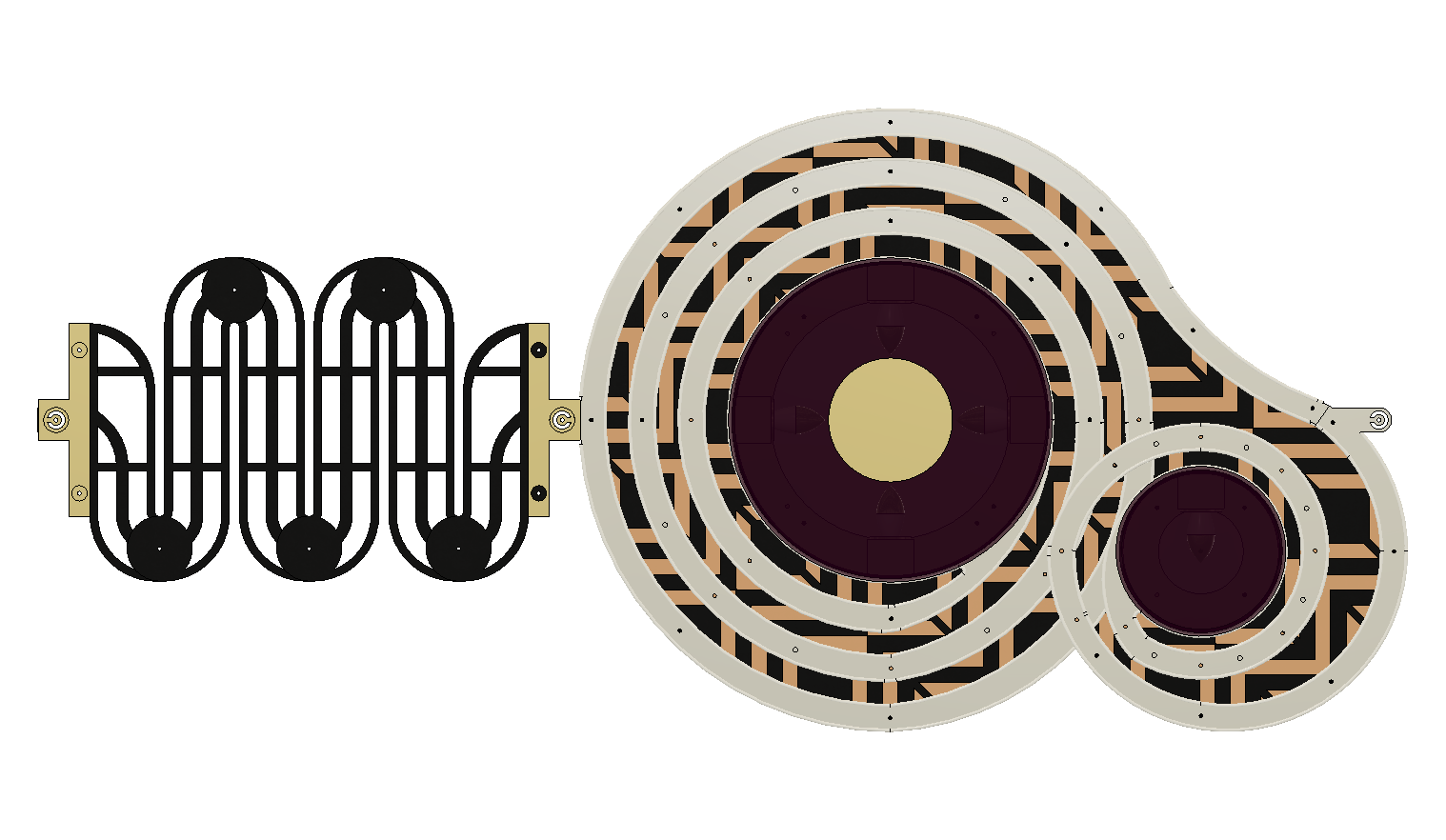
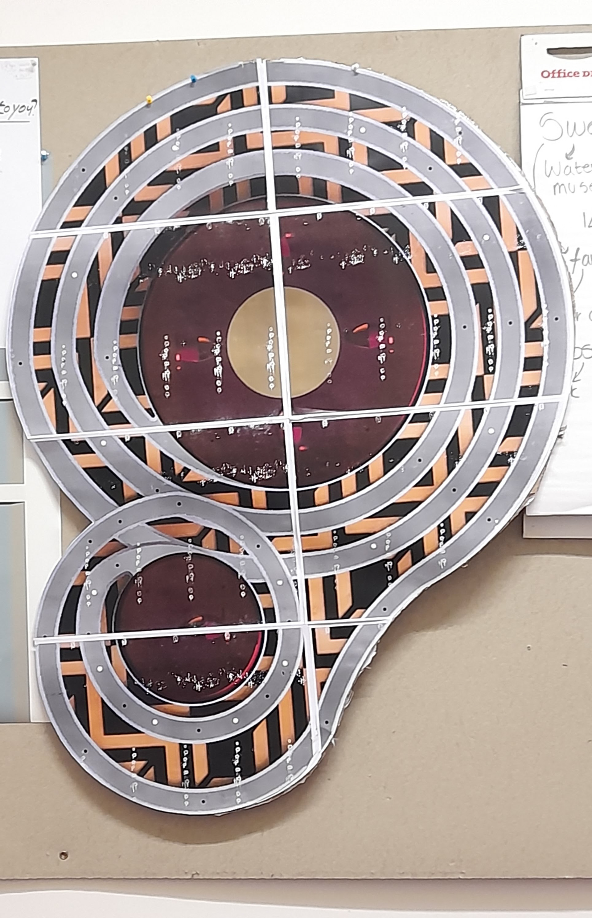
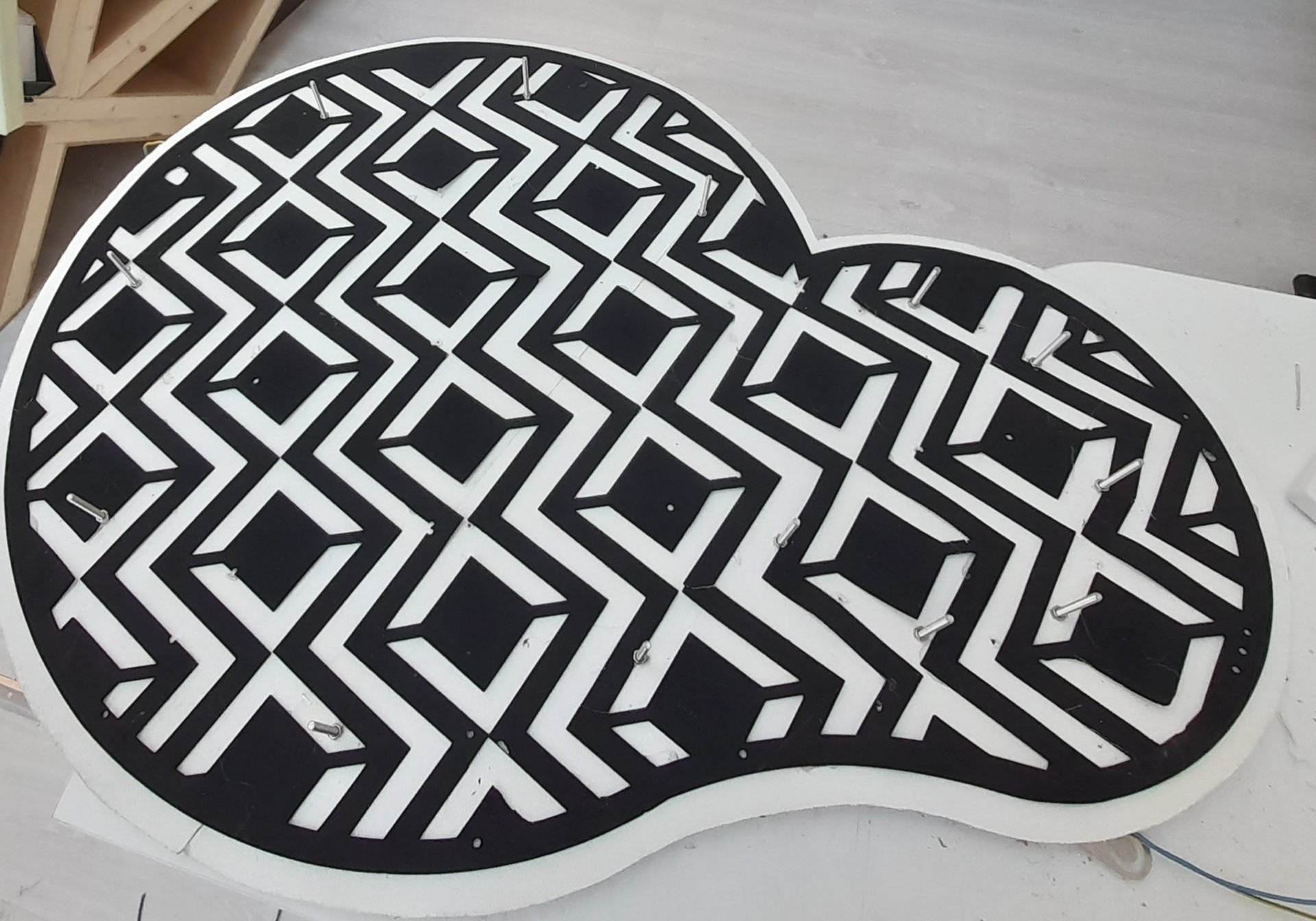
Since the double-headed snake myth is greek and due to how the mythological creature body plays a big role in the design I decided that I would look at meander patterns as an influence for the repetitive pattern aspect of the design. But essentially play a part in how the light would be fixed apart from the clamps on each end.
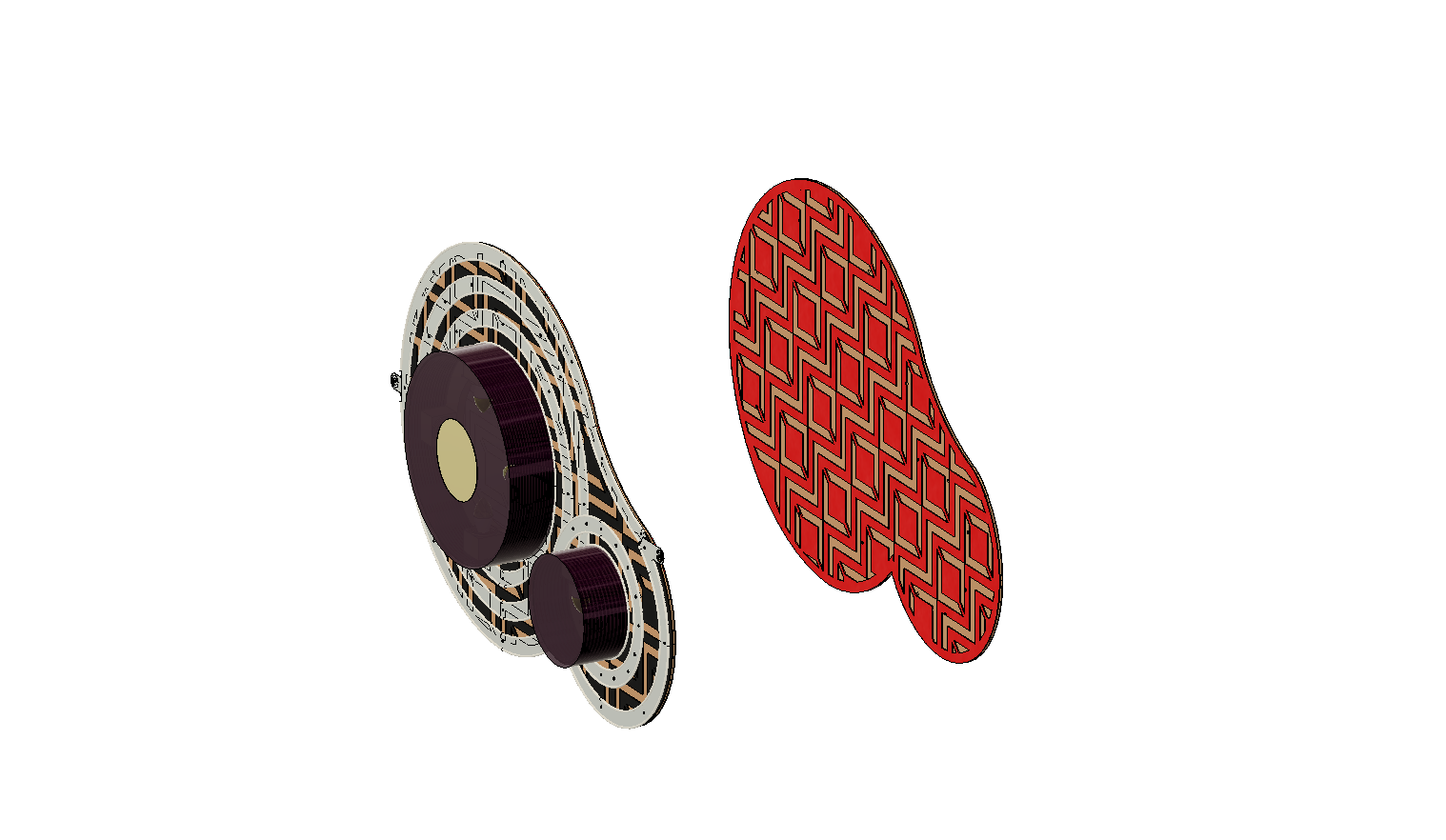
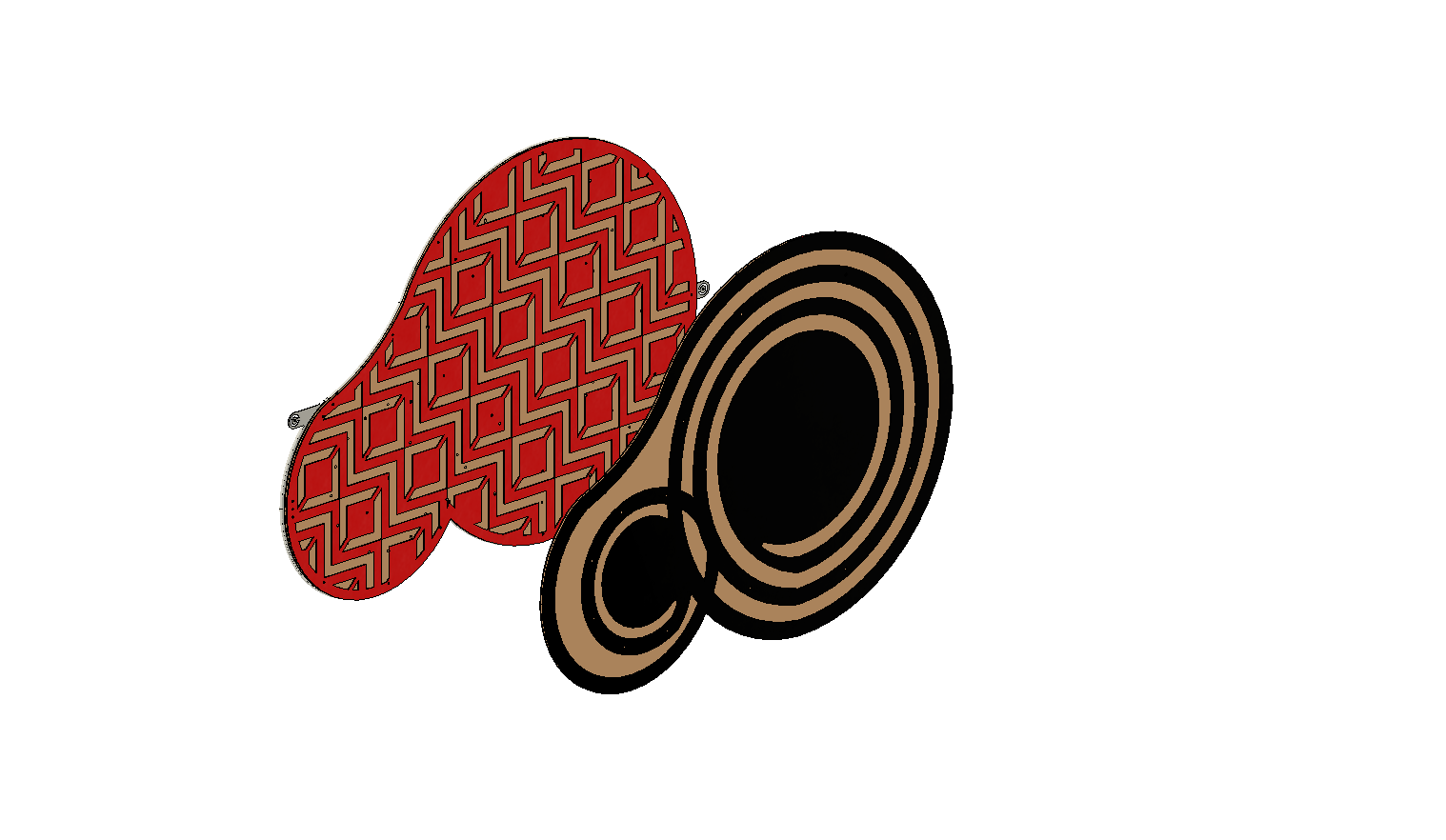
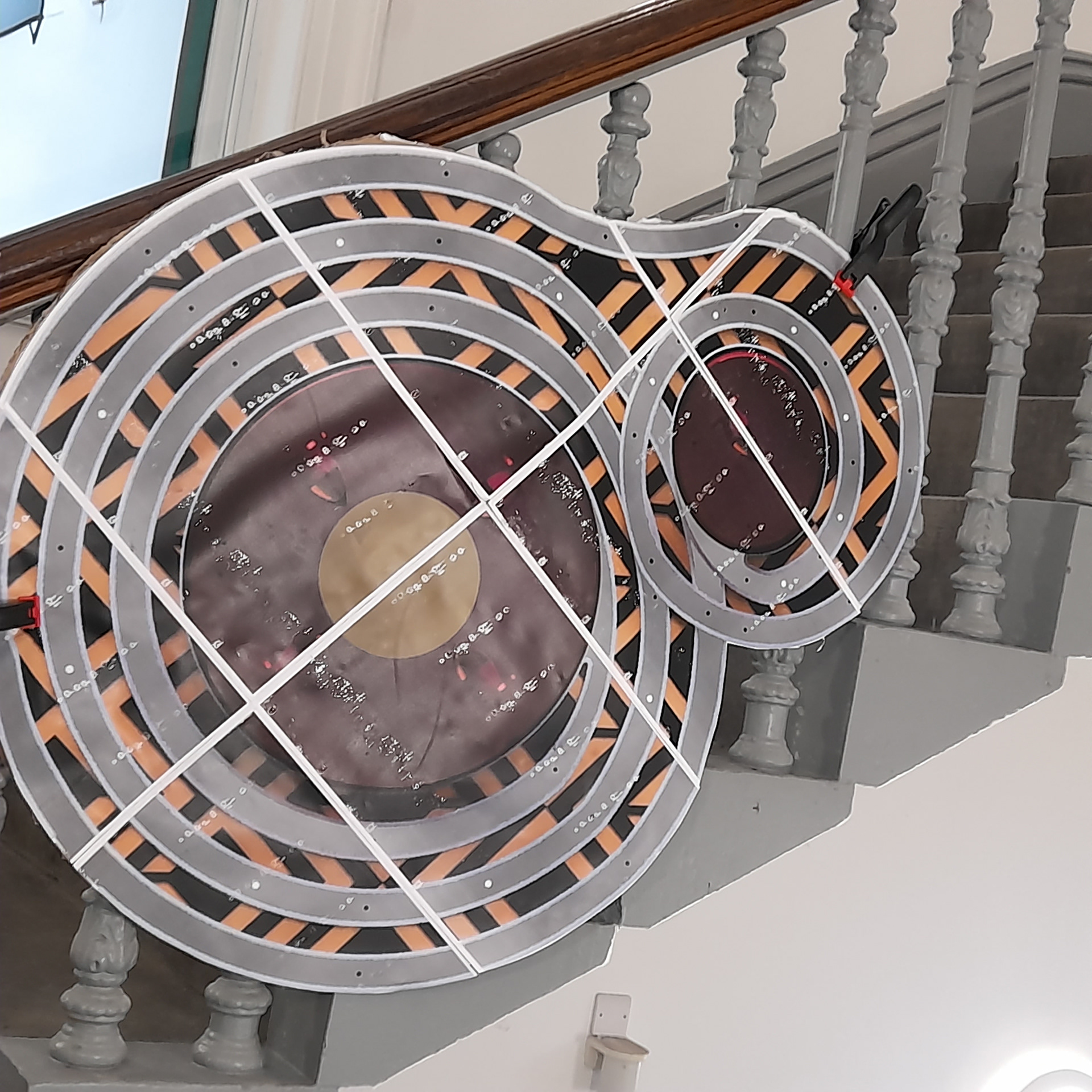
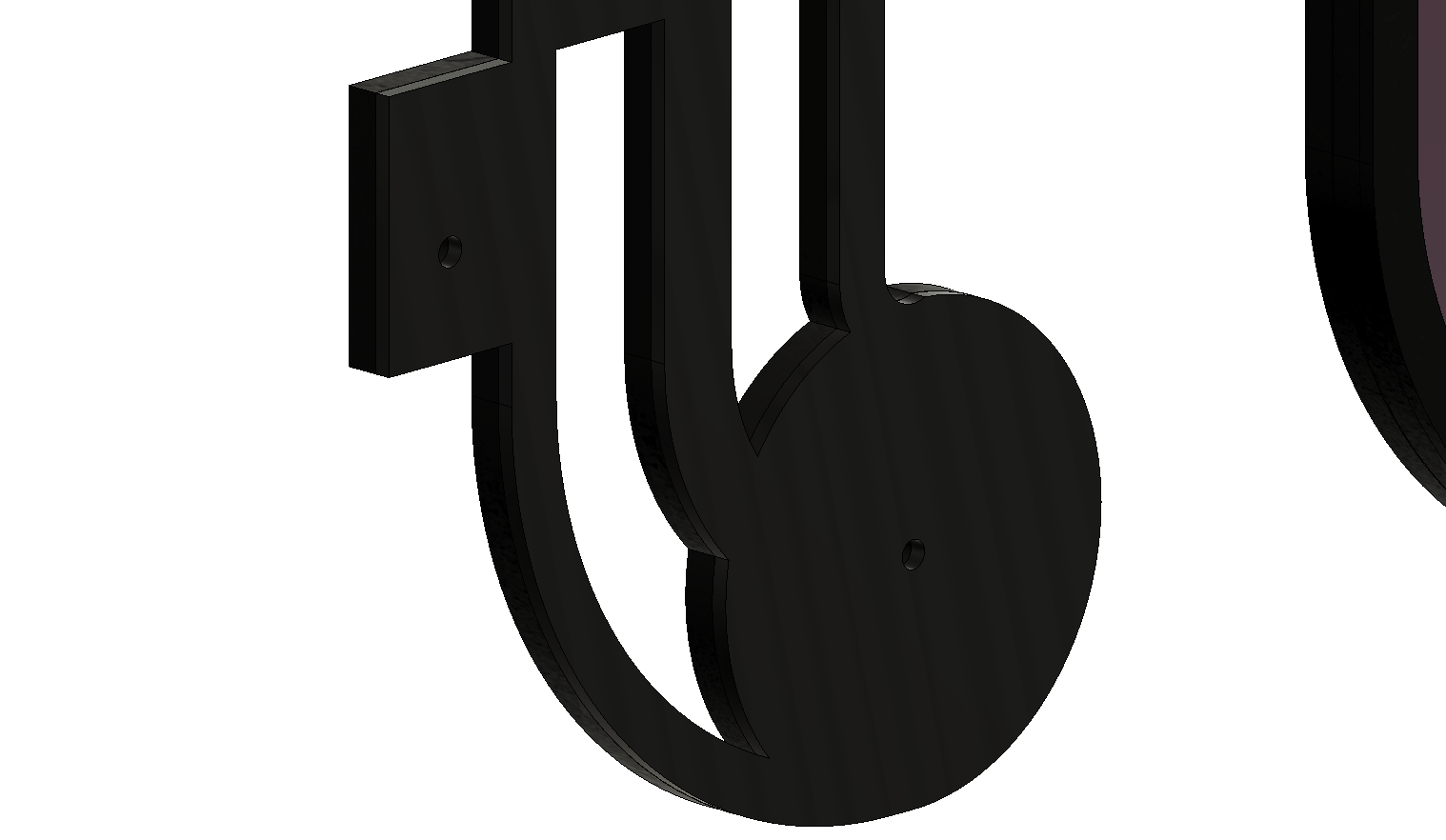
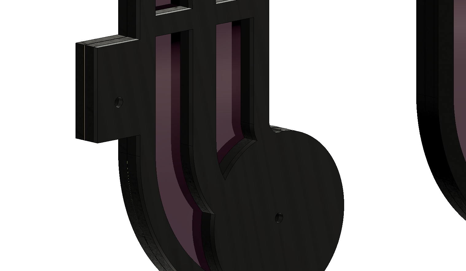
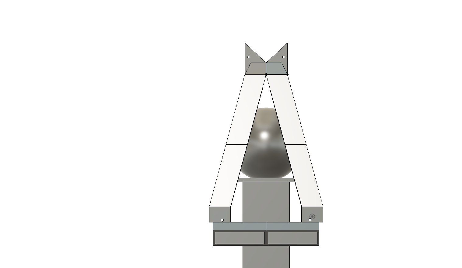
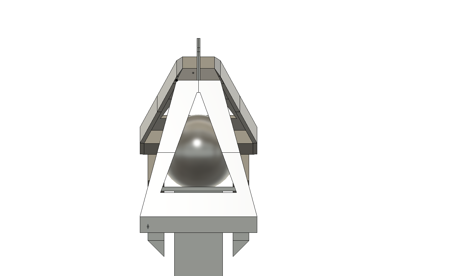
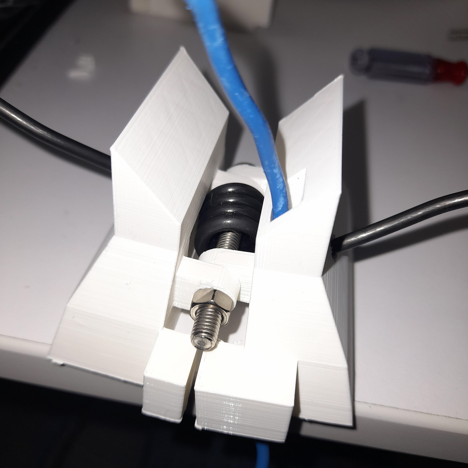
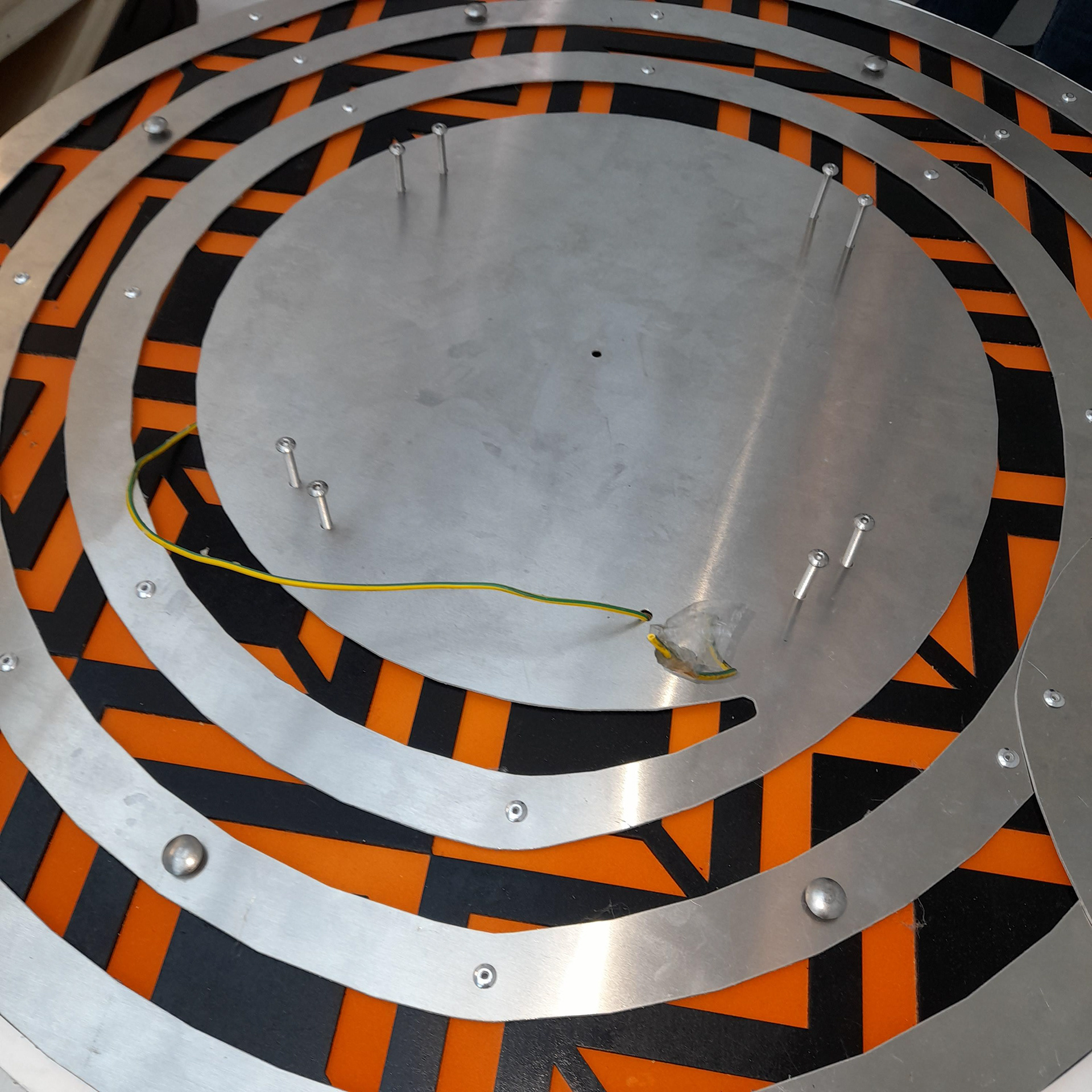
I came up with a concept as you can see. The idea is that the whorl body (aluminium) would be riveted to this and act as a front piece to a full-body clamp device. Instead of having a grip/clamp feature on the side as shown earlier on in the design process, there is now a large single one.
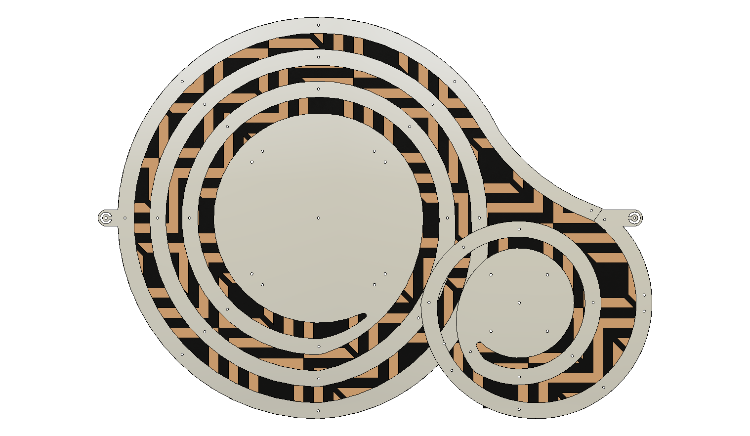
The red bits represent the area where the bolts would be located which would hold the back piece of the clamp
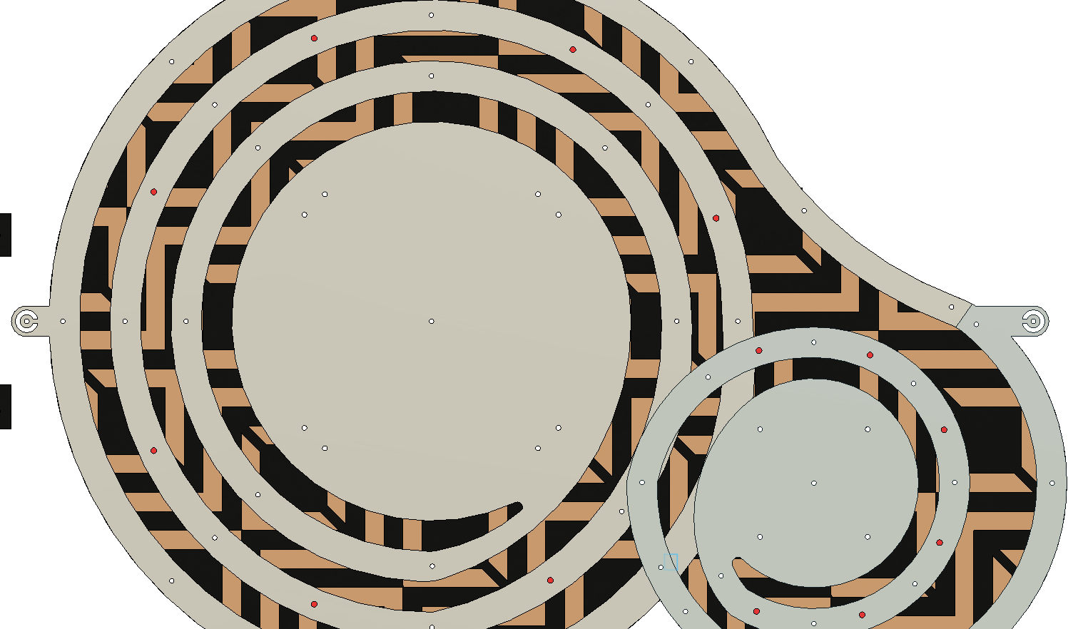
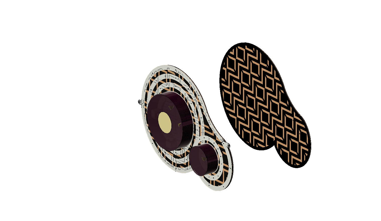
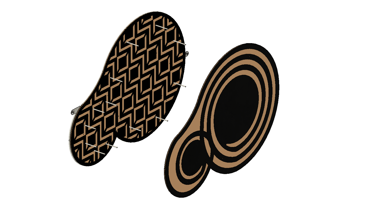
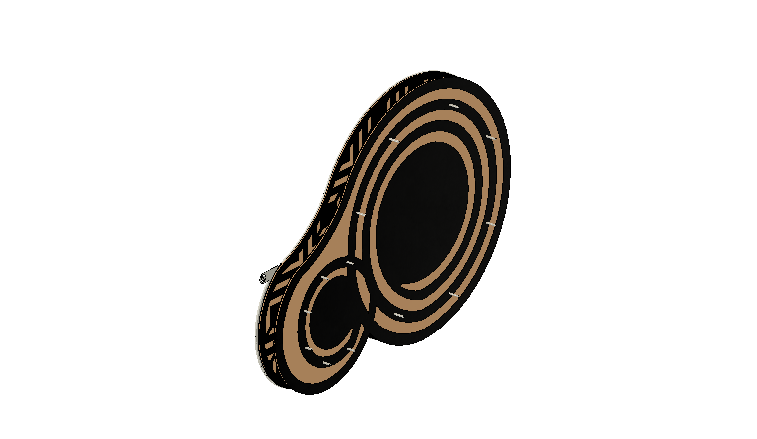
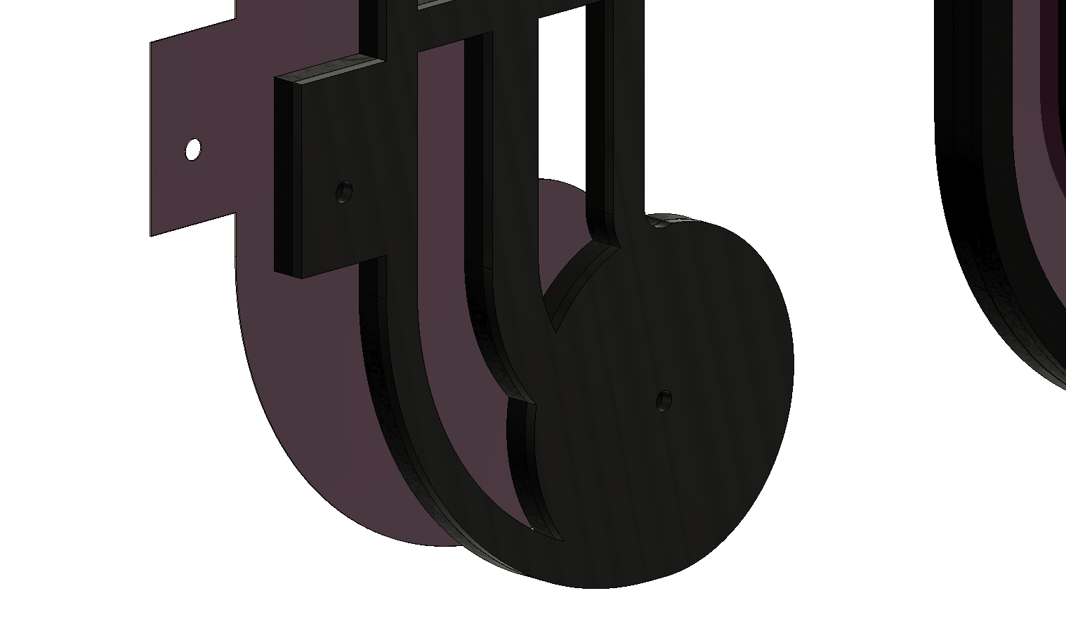
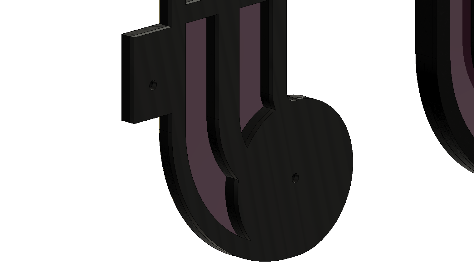
In between the front part and the back part, there are two rubber patterns attached to the board. The rubber patterns are the same as the one on the front part. The back part outside as in the behind feature is the same shape as the aluminium whorl but it's in wood board instead. The red patterns below are just to show that these two pieces are rubber and not board.
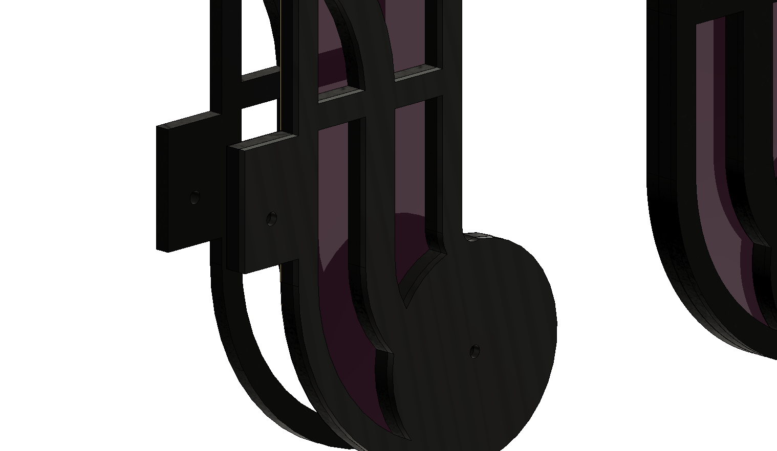
So you would position the front part in between the spindles and then place the back on and then tighten with nuts and the rubber insides will hold it in place.
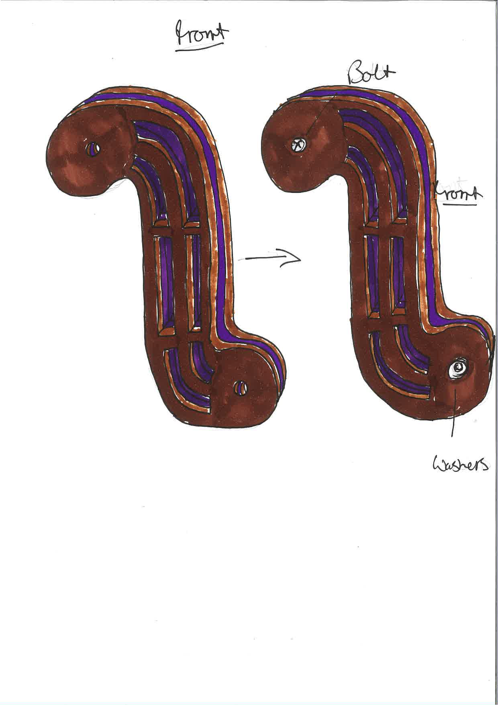
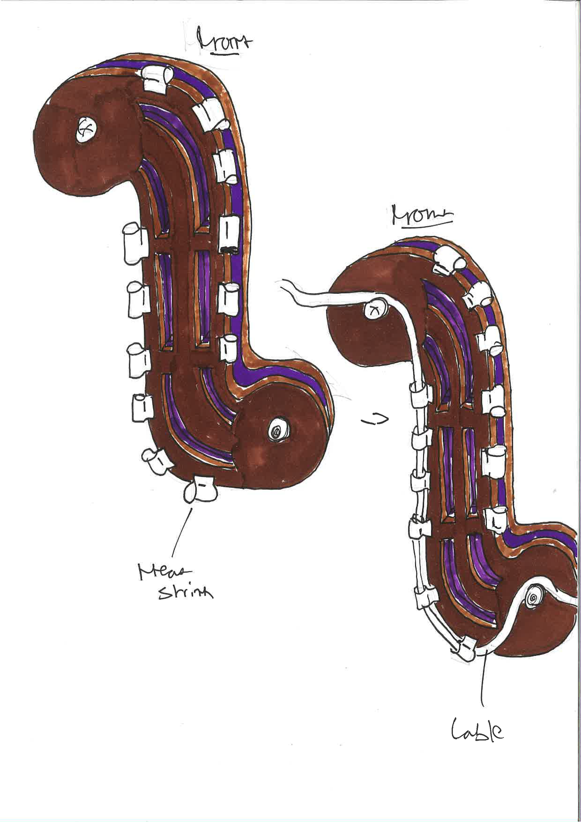
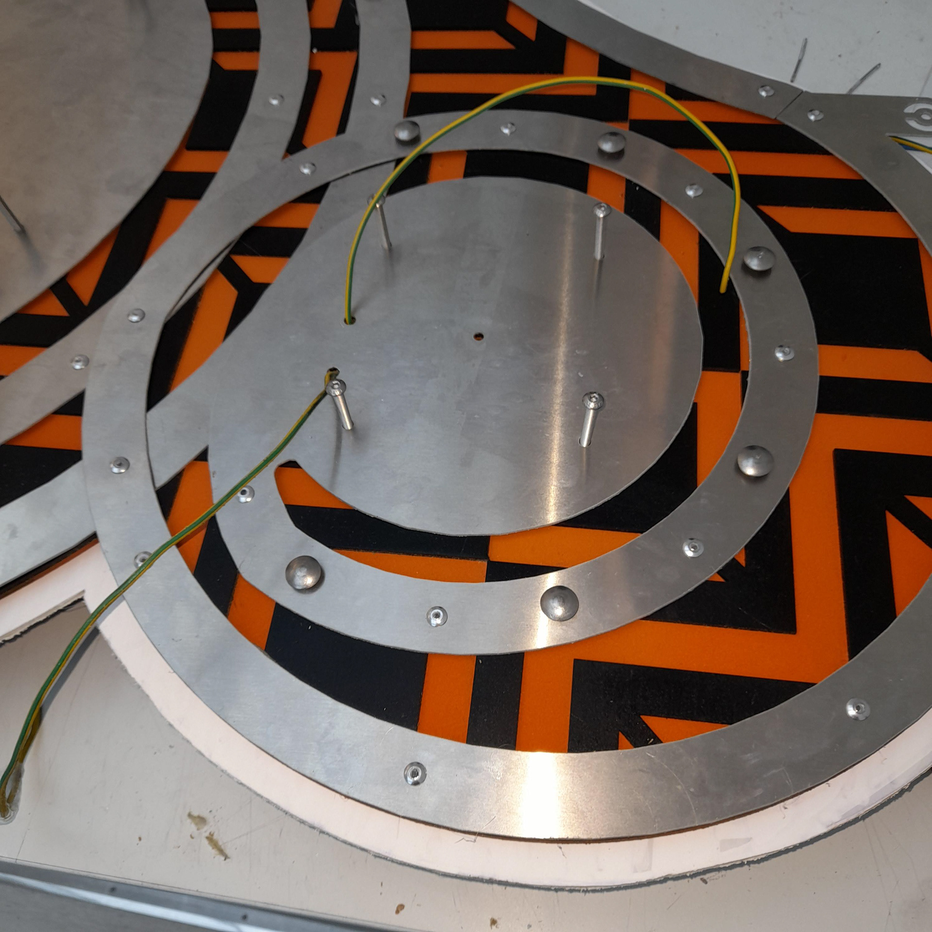
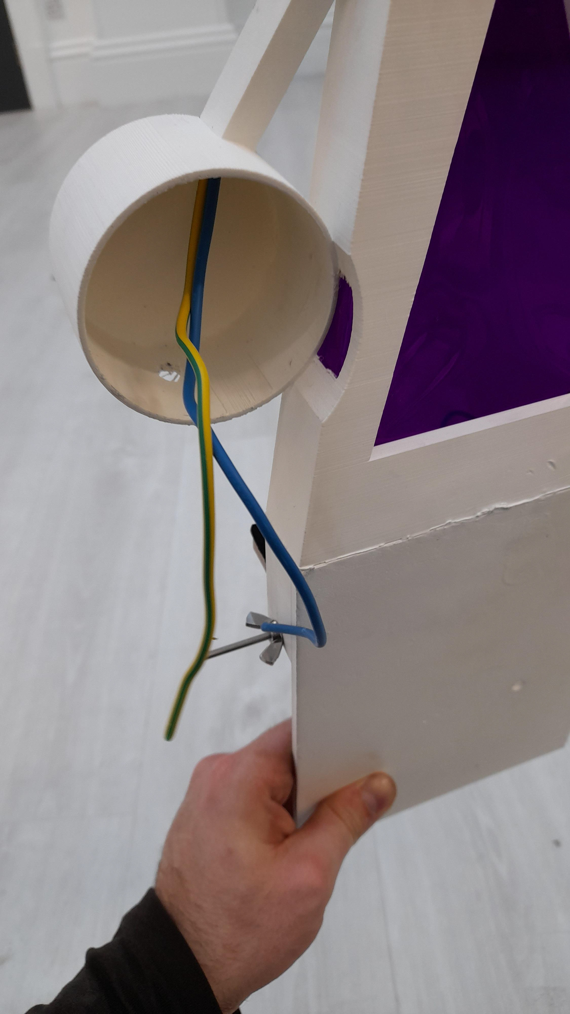
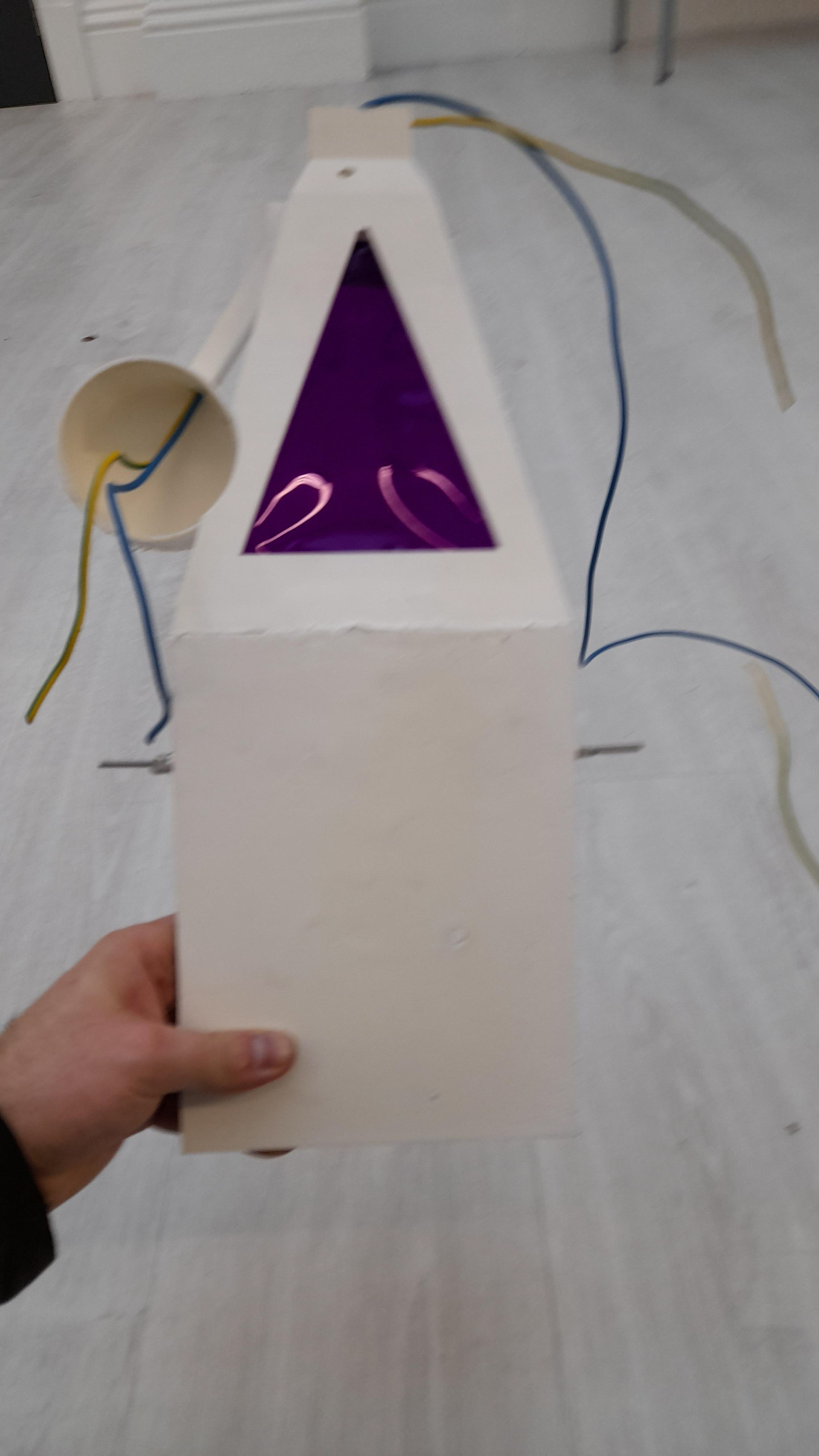
The gold like shapes on the end of the adjustable pattern/ moving body is the start of the design part to do with the vertebrate aspect. As you can see these are only quick concepts and will change. Although if you look at the cable in between the heat shrink below it reminds you of a bone-like appearance so I'm thinking that I will make this noticeable on the design.
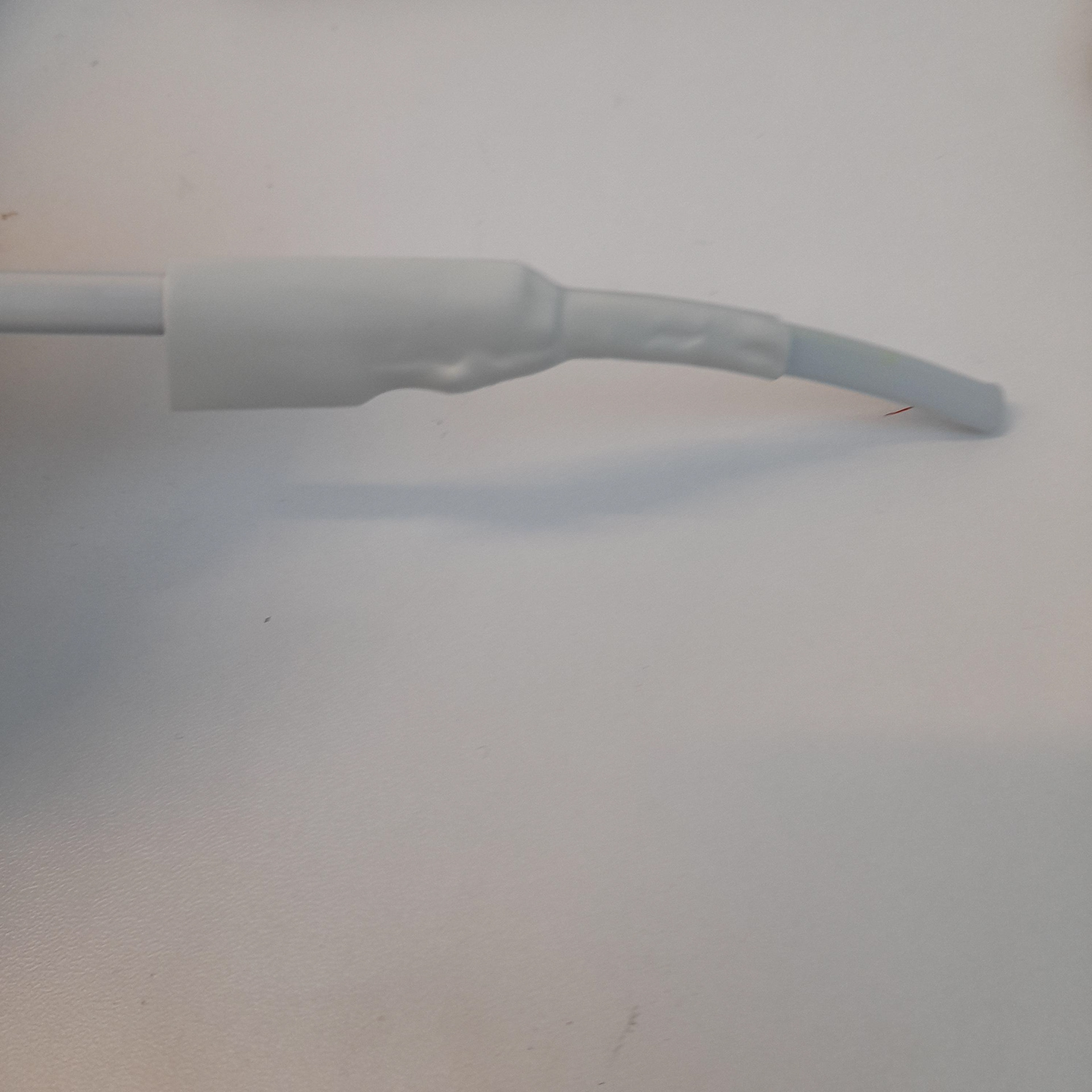
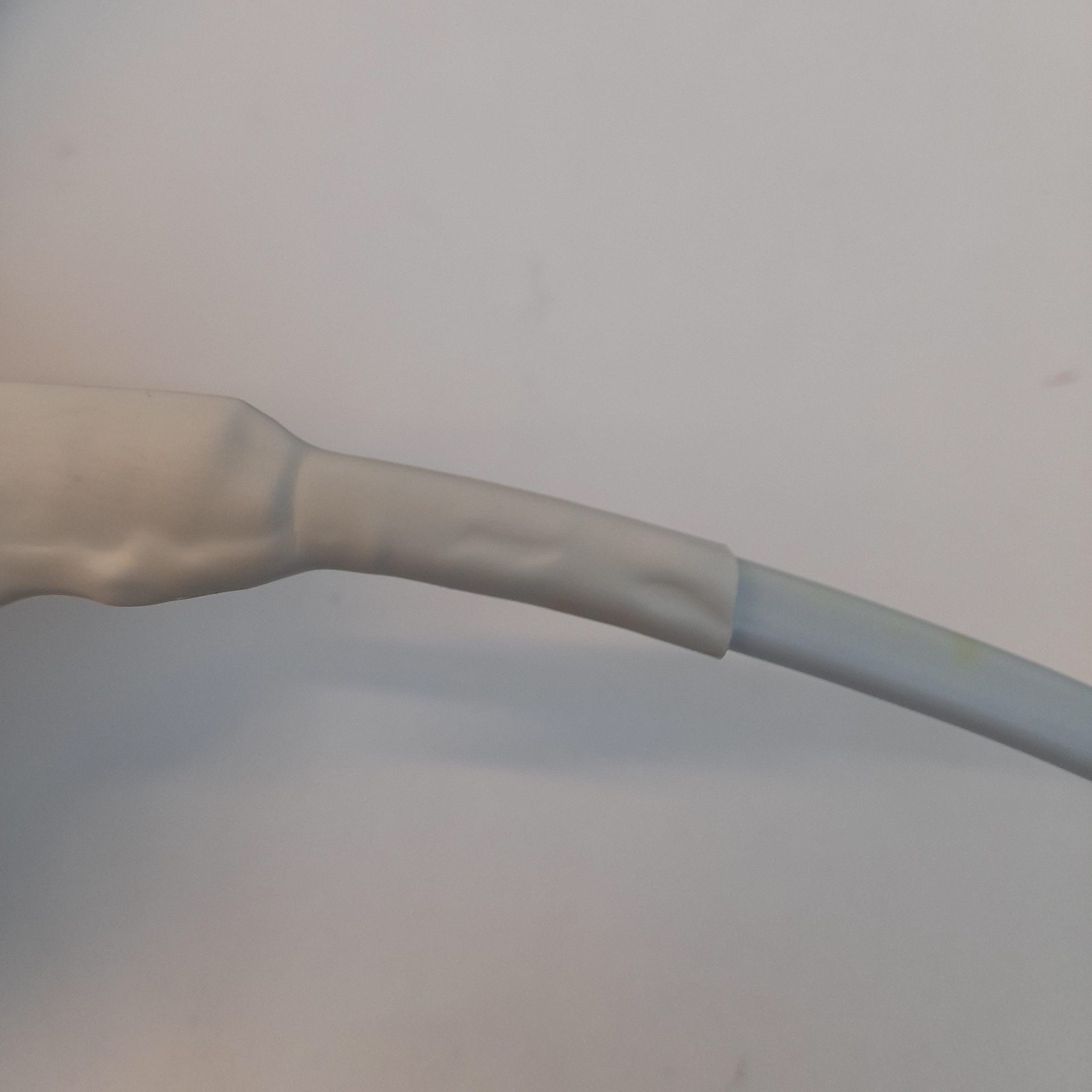
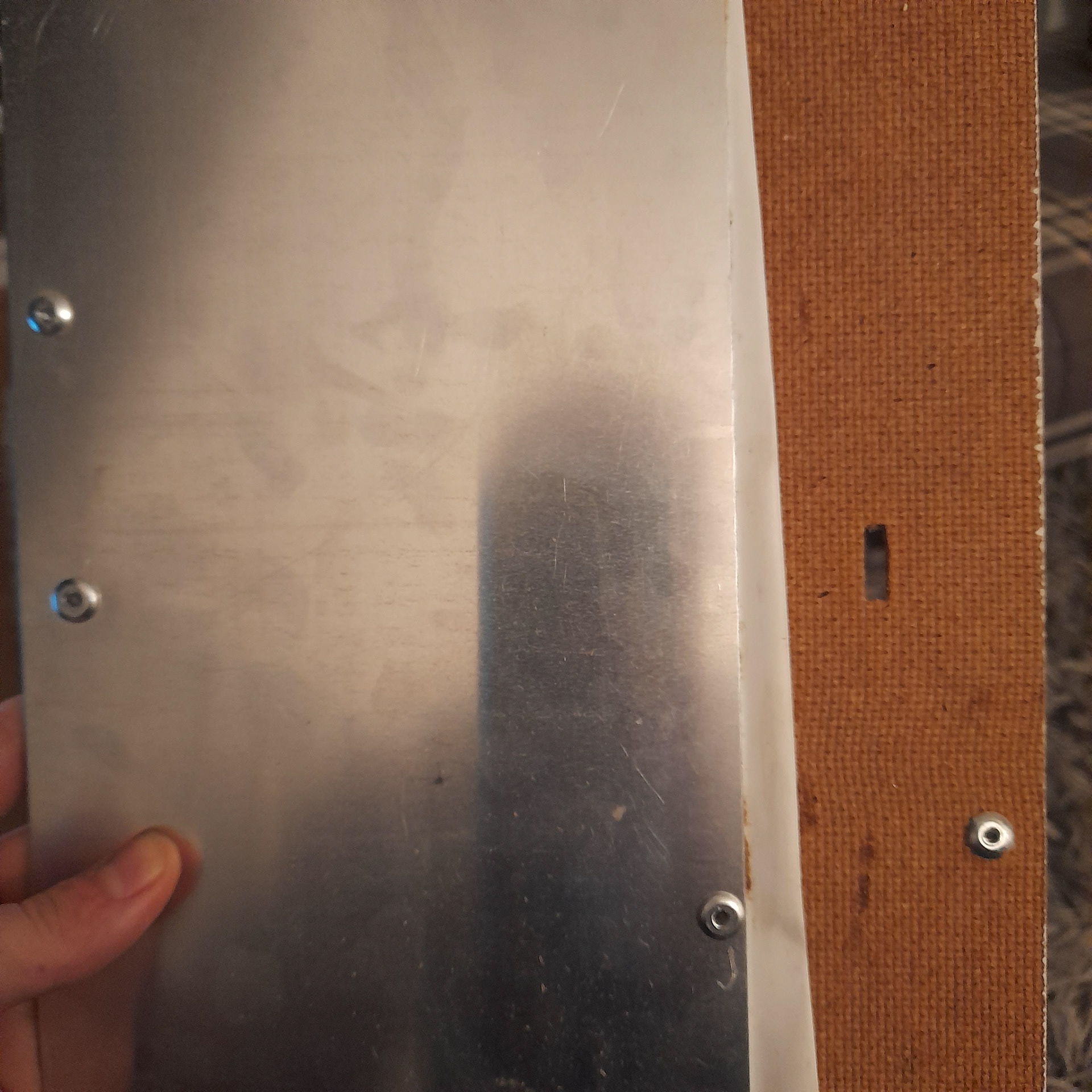
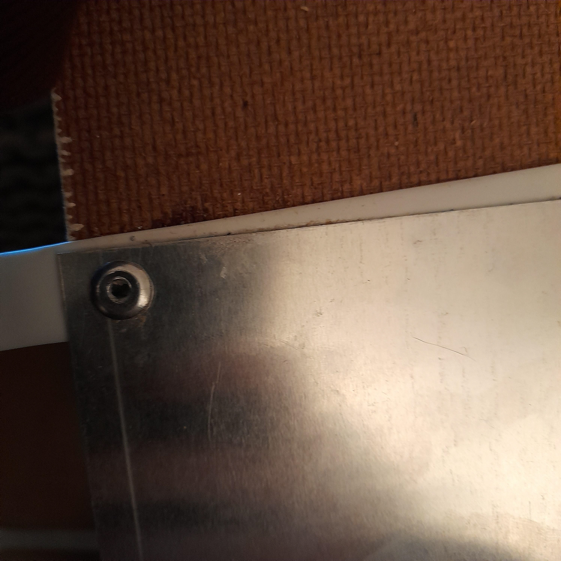
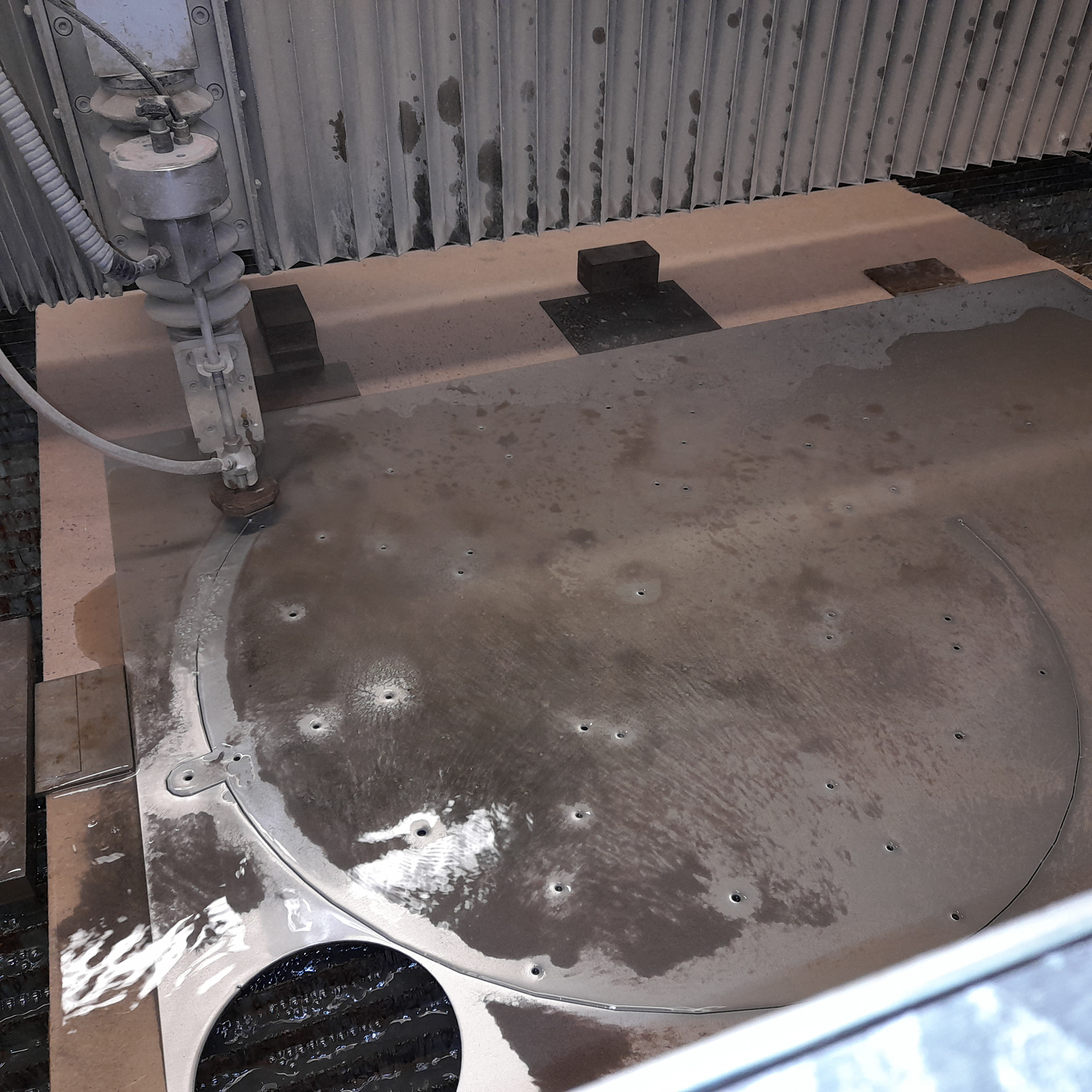
So, I did a trial run. The metal is 1mm thick and the wood is 4mm thick. The rivet size is 4.8 x 10mm. I will need longer ones for the actual model. The idea behind glueing the heat shrink in between the metal and wood didn’t work. Instead, I tried one attempt of riveting the heat shrink as well. This worked and if I were to pull it, it would take a lot of force to rip it out. Therefore, in the actual model, thicker heat shrink will be used. The one in this mock is 9.5mm. I’ll most likely need a 15mm. Also if I’m riveting it in place I won’t need to shrink it.
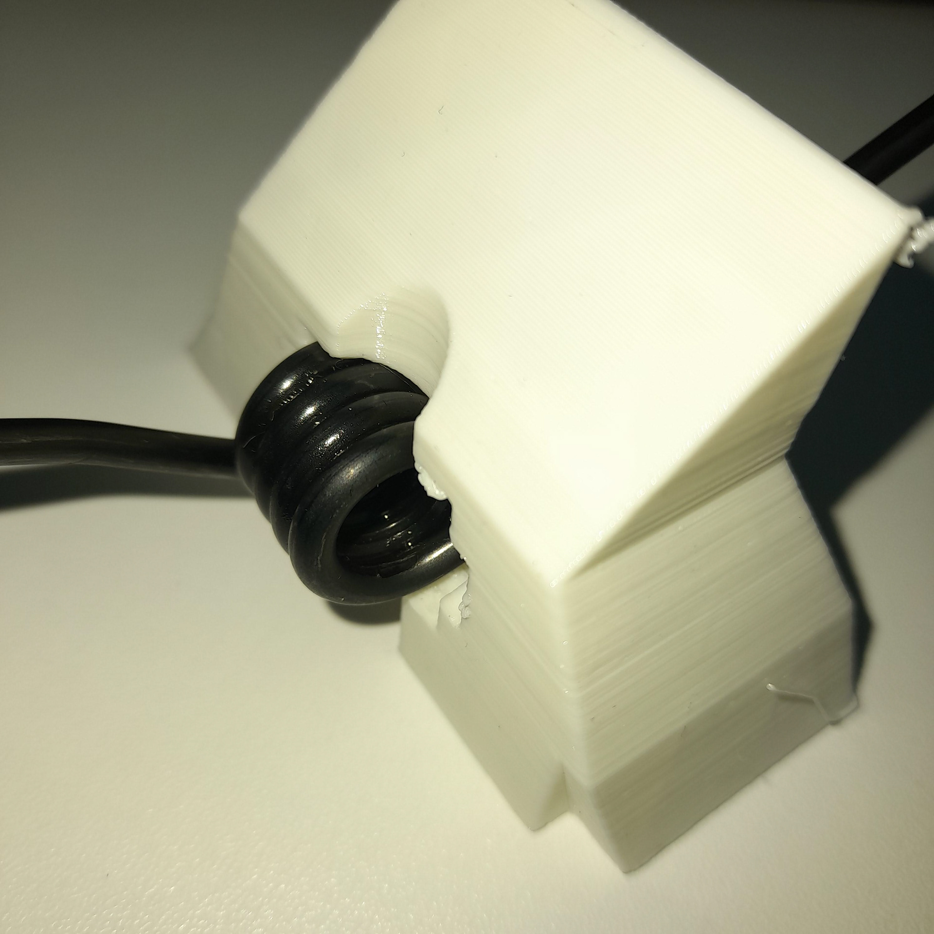
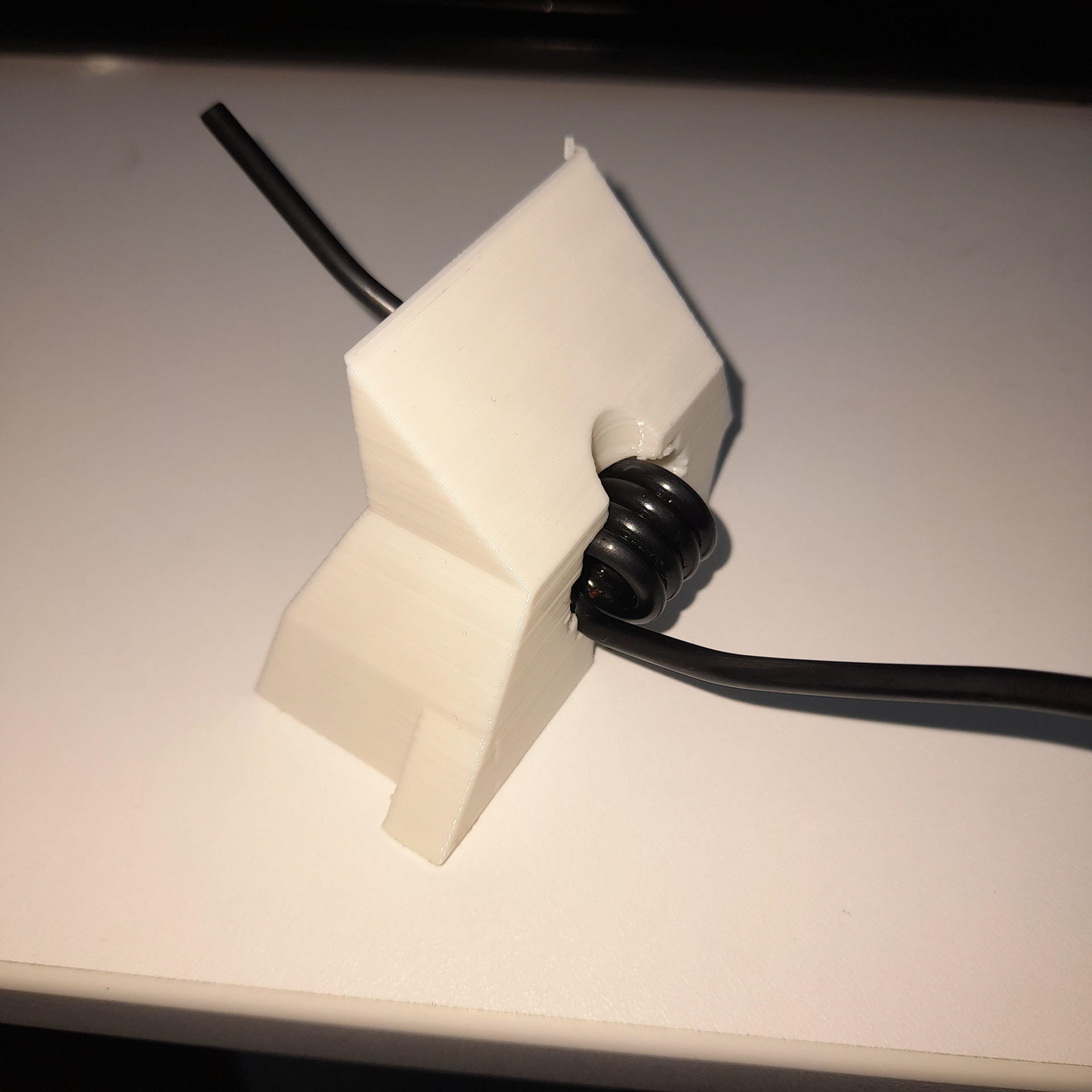
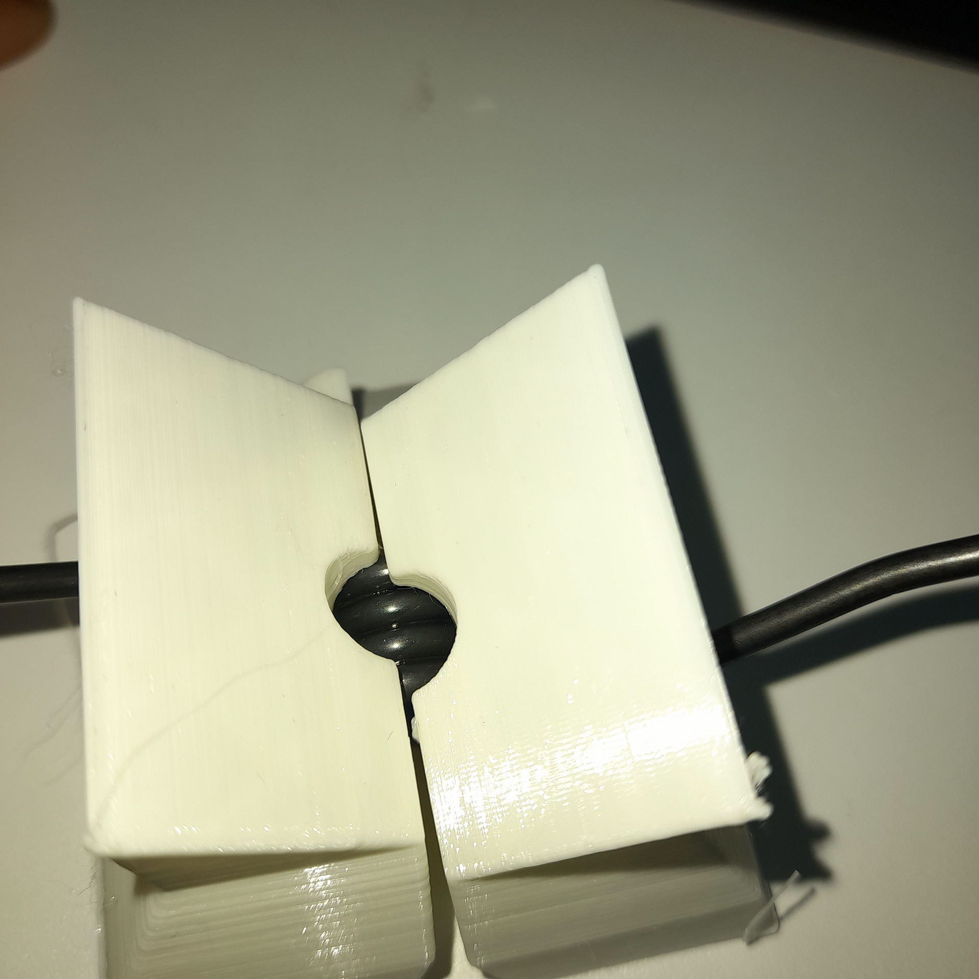
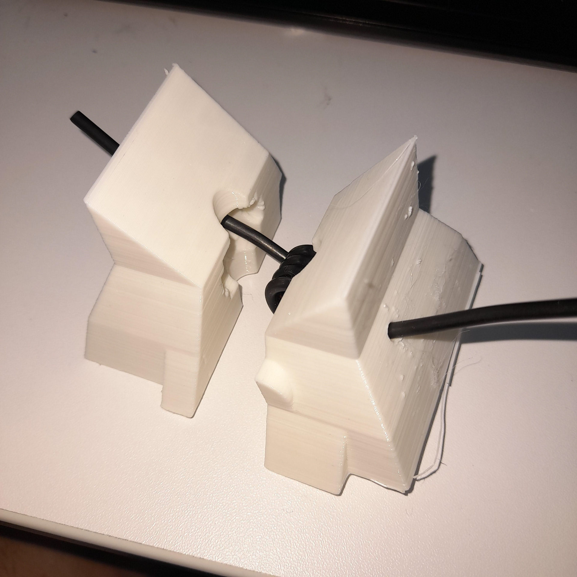
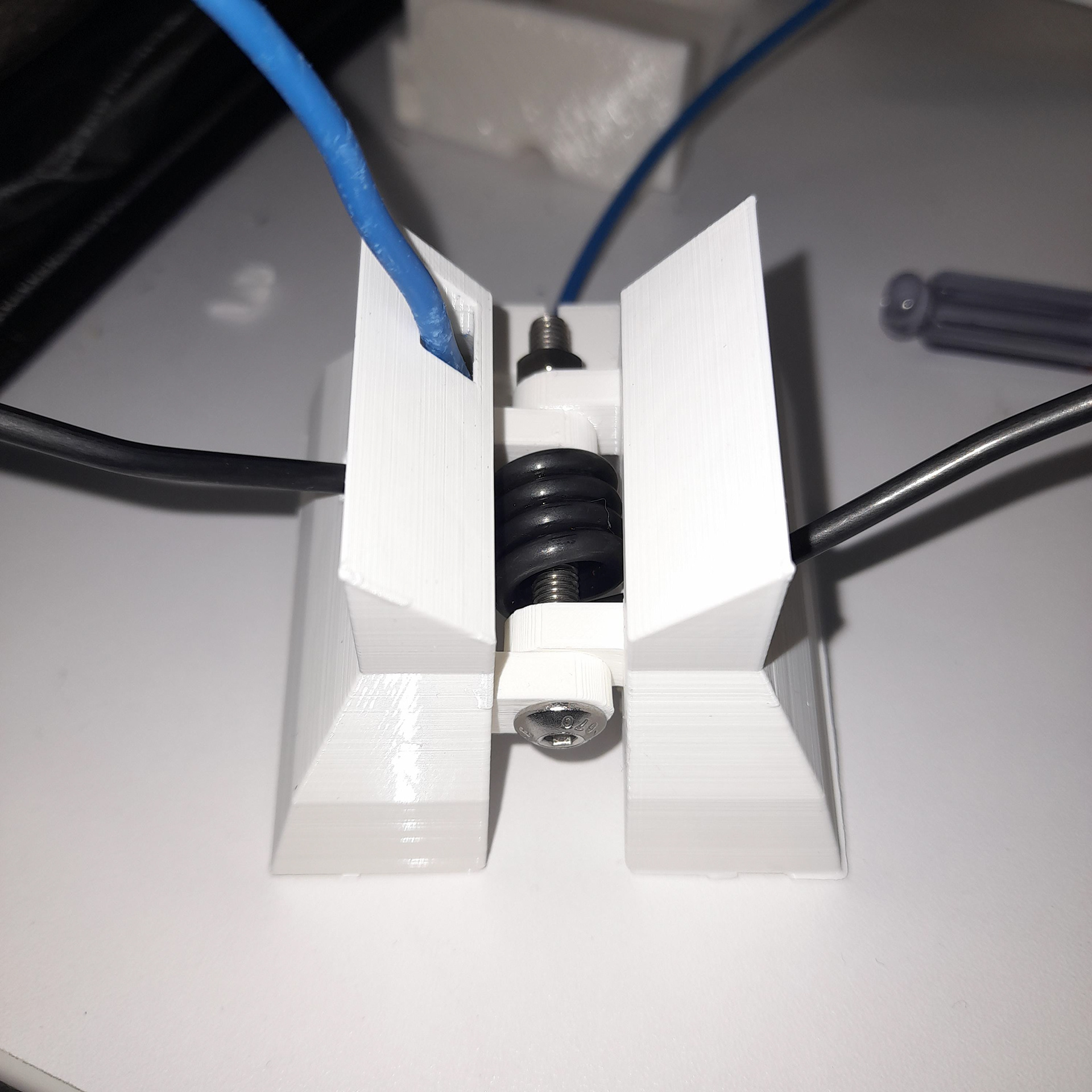
The first video and second video are both attempts at figuring out how the cable should be placed on the moveable parts. In the first, you’ll notice that the wire on the bottom sticks. This is not what I want. The second shows how I prevented this by wrapping the bottom cable around the same path as the top cable. They are bother wrapped around the bolt. However, the heat shrink had been cut into pieces because if whole there would have been too much resistance. I will need to add something in between the gaps to hide the wire moving as well.
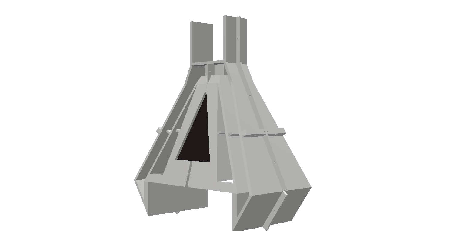
3rd model of the clamp/grip on each end
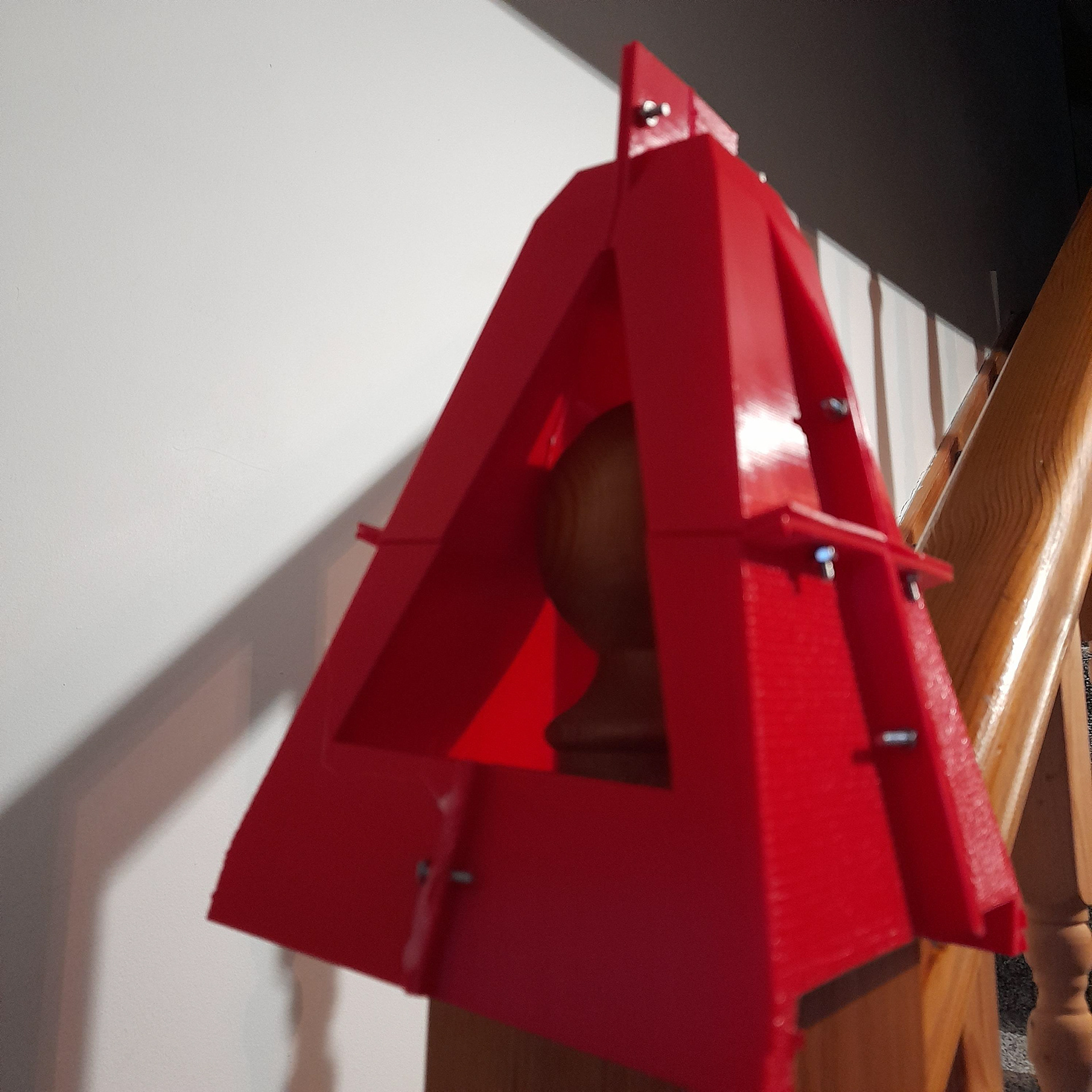
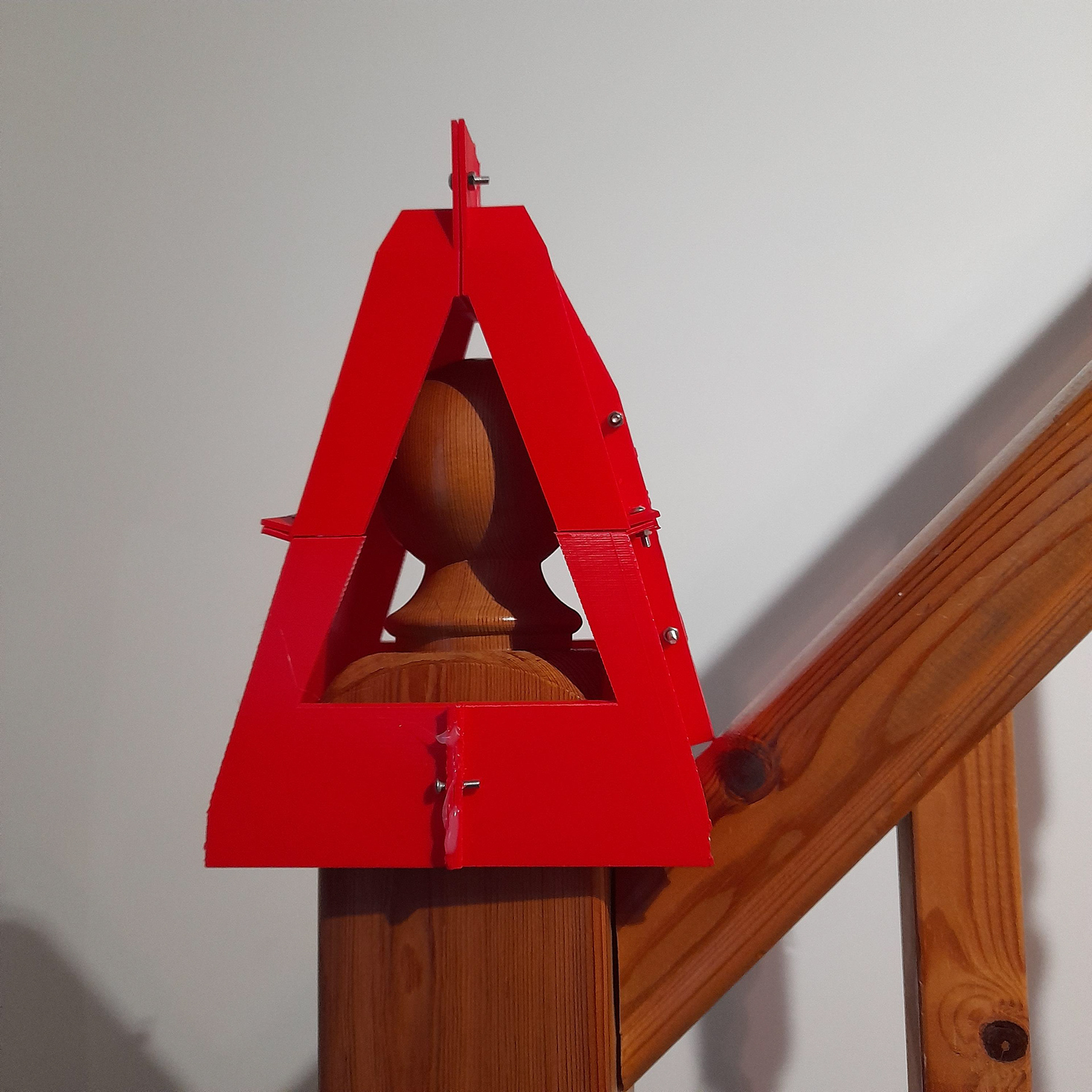
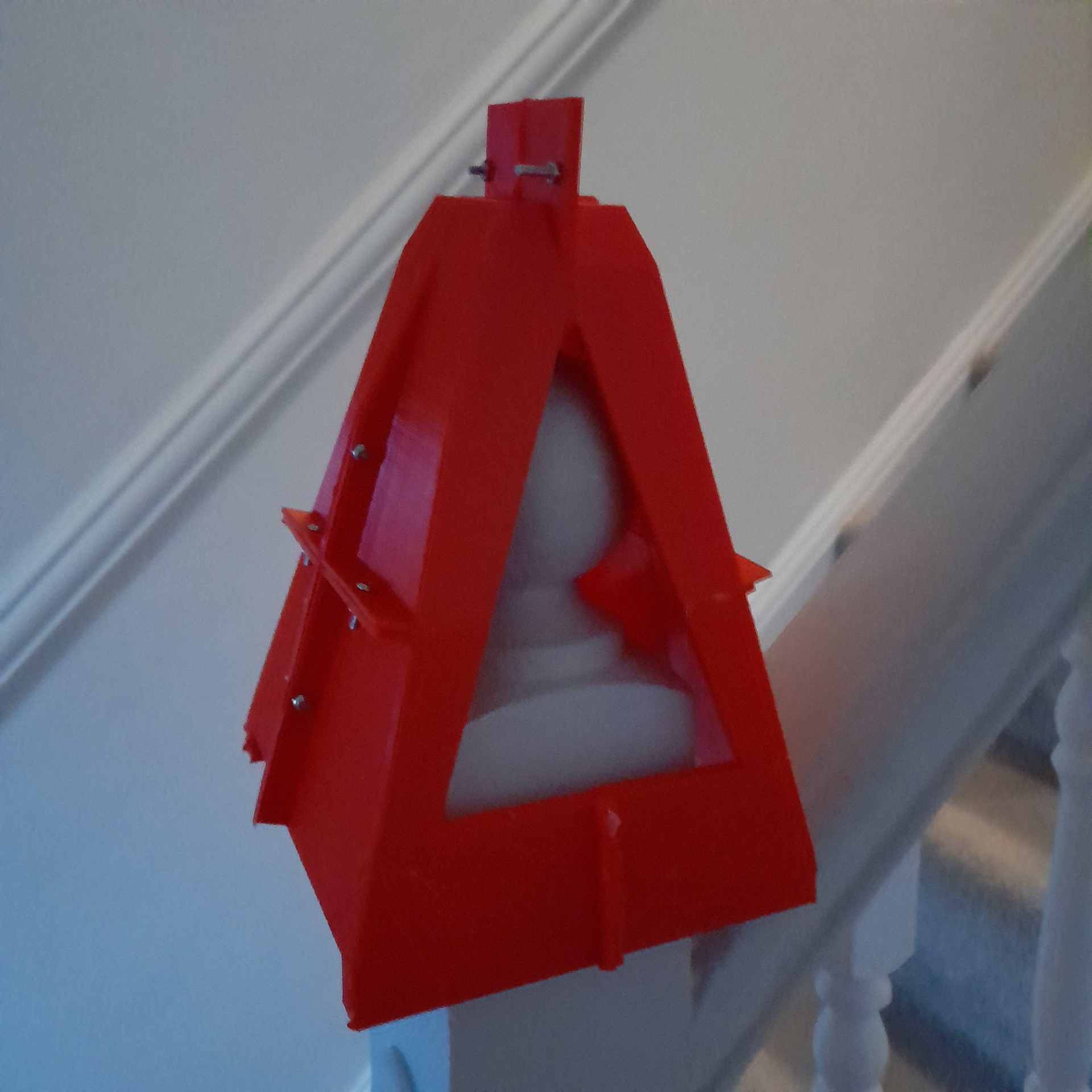
Below shows my initial idea of printing the clamp in multiple pieces. I realised soon after this would be a bad idea because it would be too much to put together. Hence I did another take on it which required fewer features. The way it would function would involve it being placed over a newel cap on a staircase. Then there would be adjustable grips on each side that would tighten the hold.
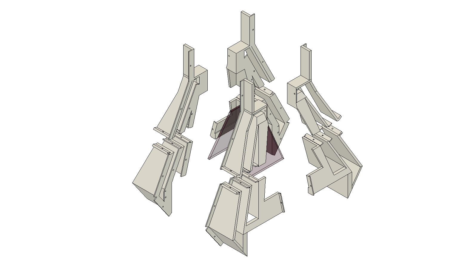
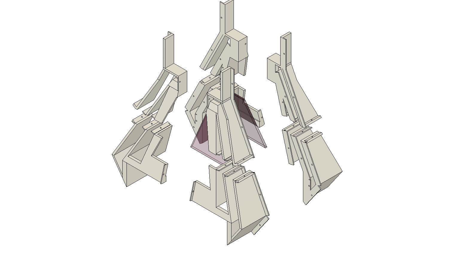
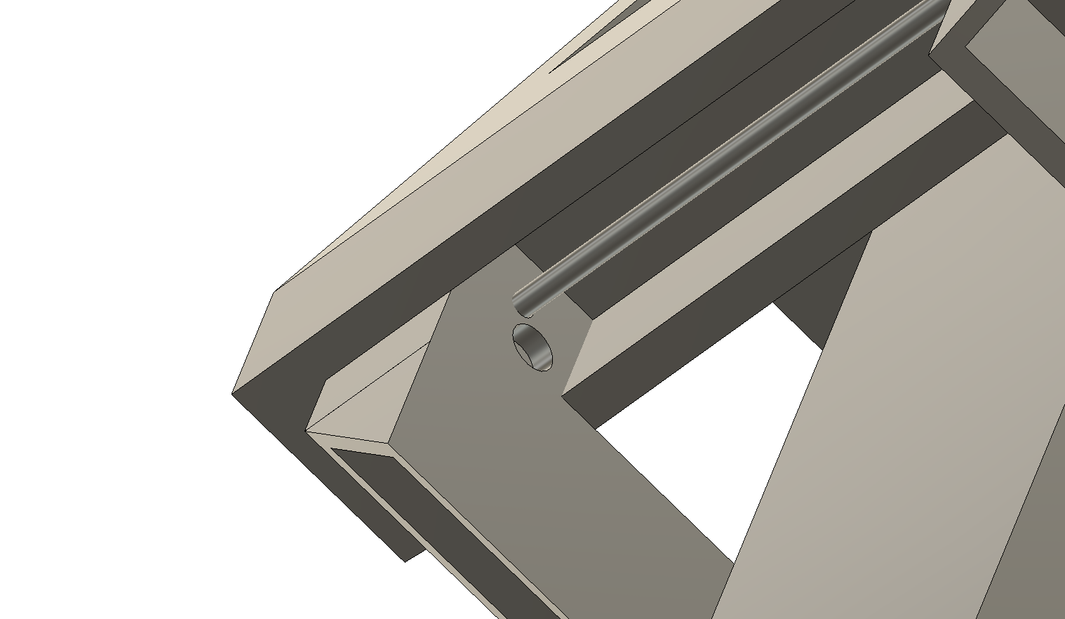
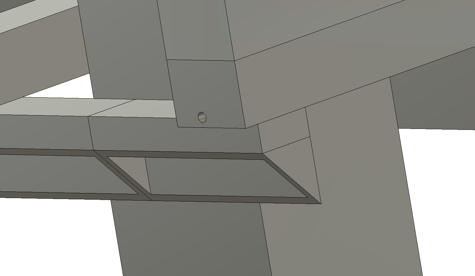
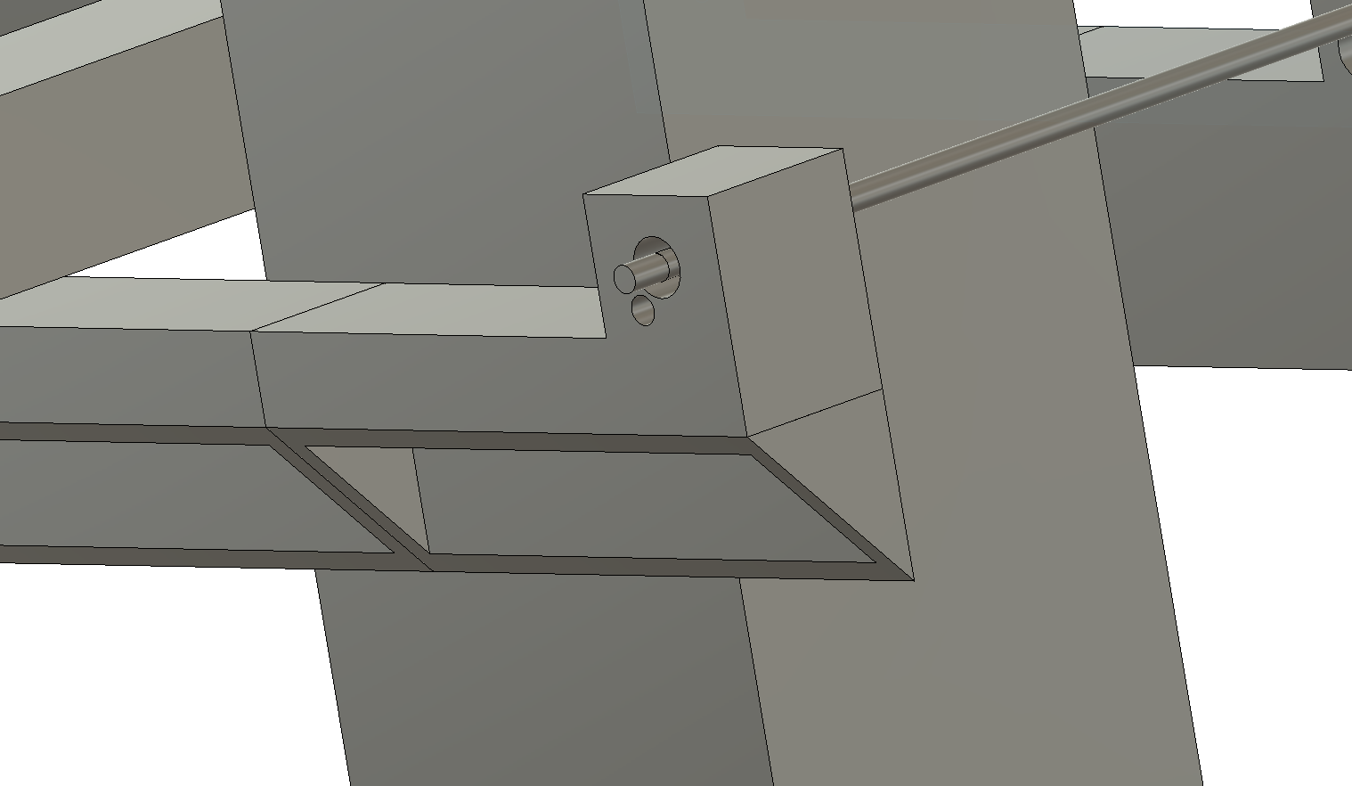
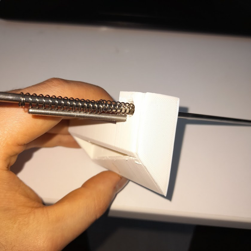
The image above shows part of one of the grips. the way it would work is that they would slide on a metal rod. The pieces would be tightened down or loosened by a bolt nut and springs. Causing the tension needed to create the grip effect.
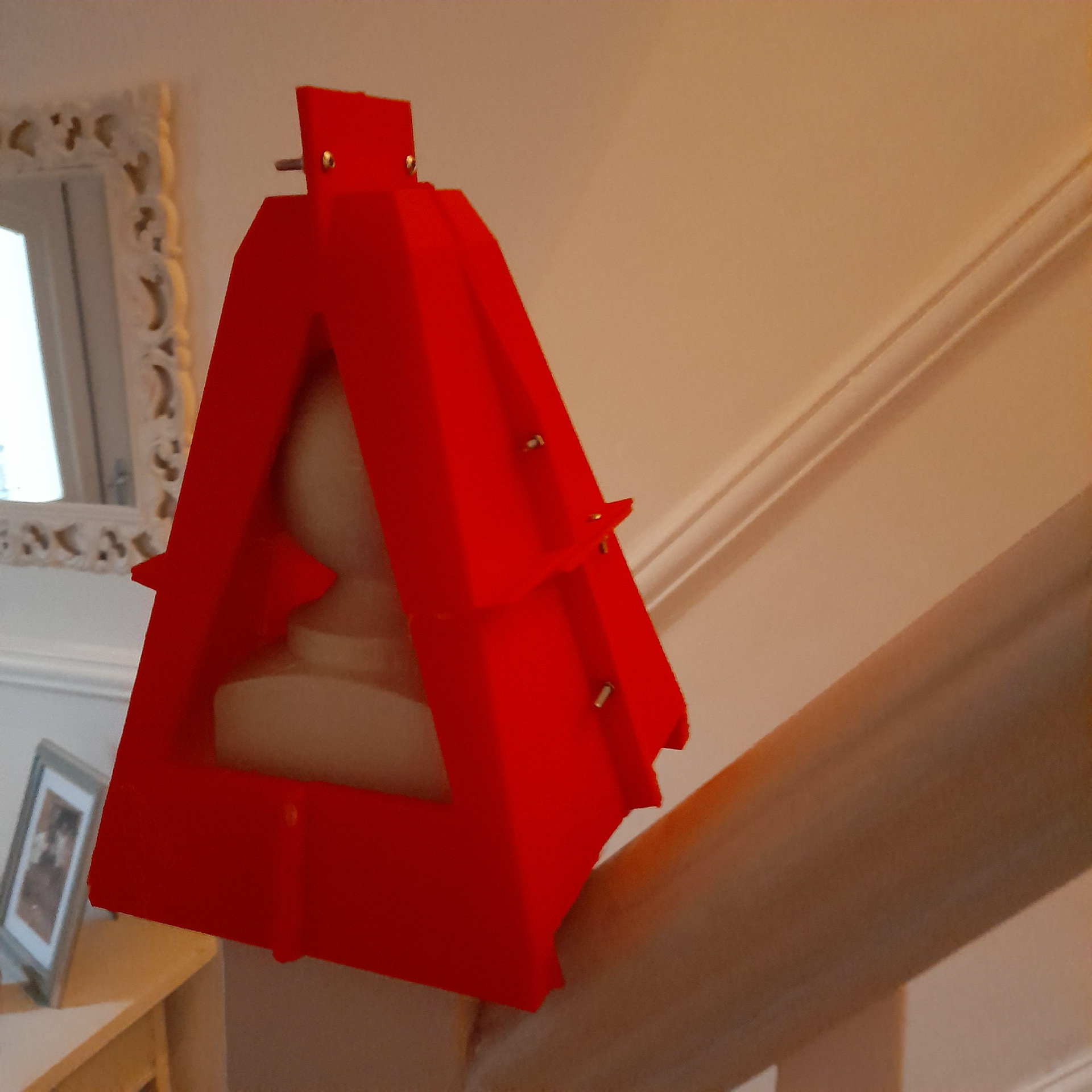
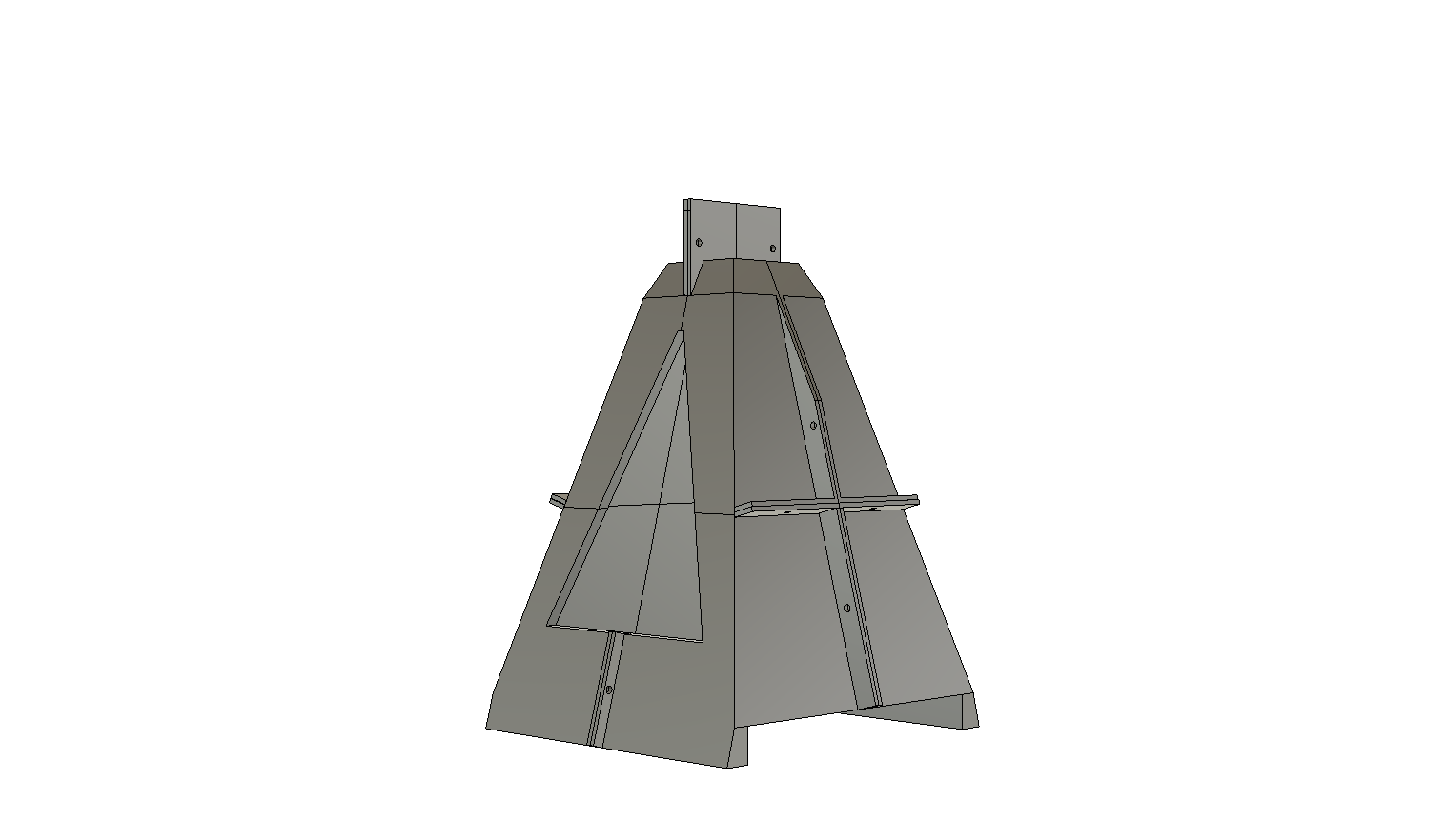
Before I continued with this concept, as in editing further on fusion 360, I printed off a model just to check the dimensions
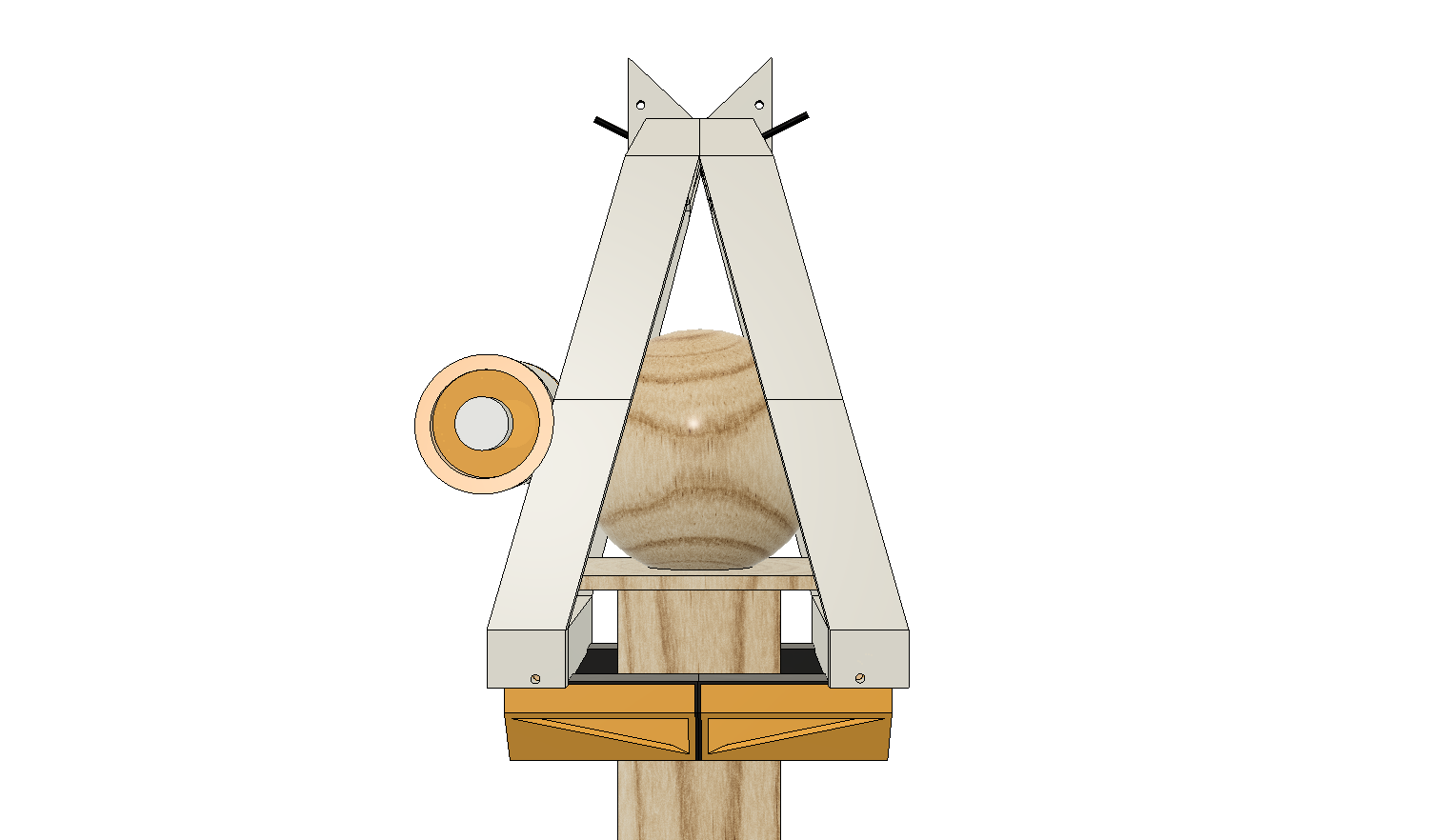
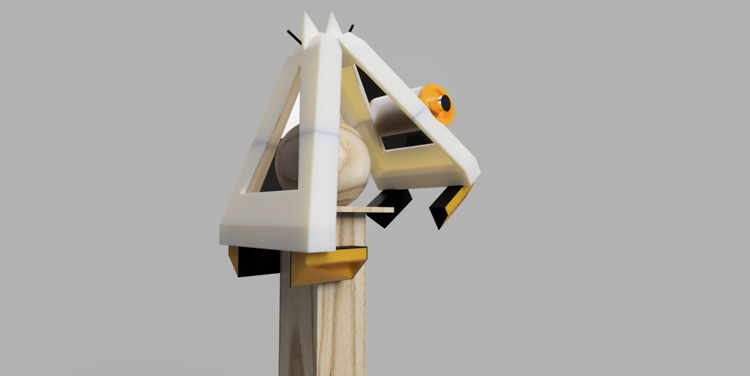
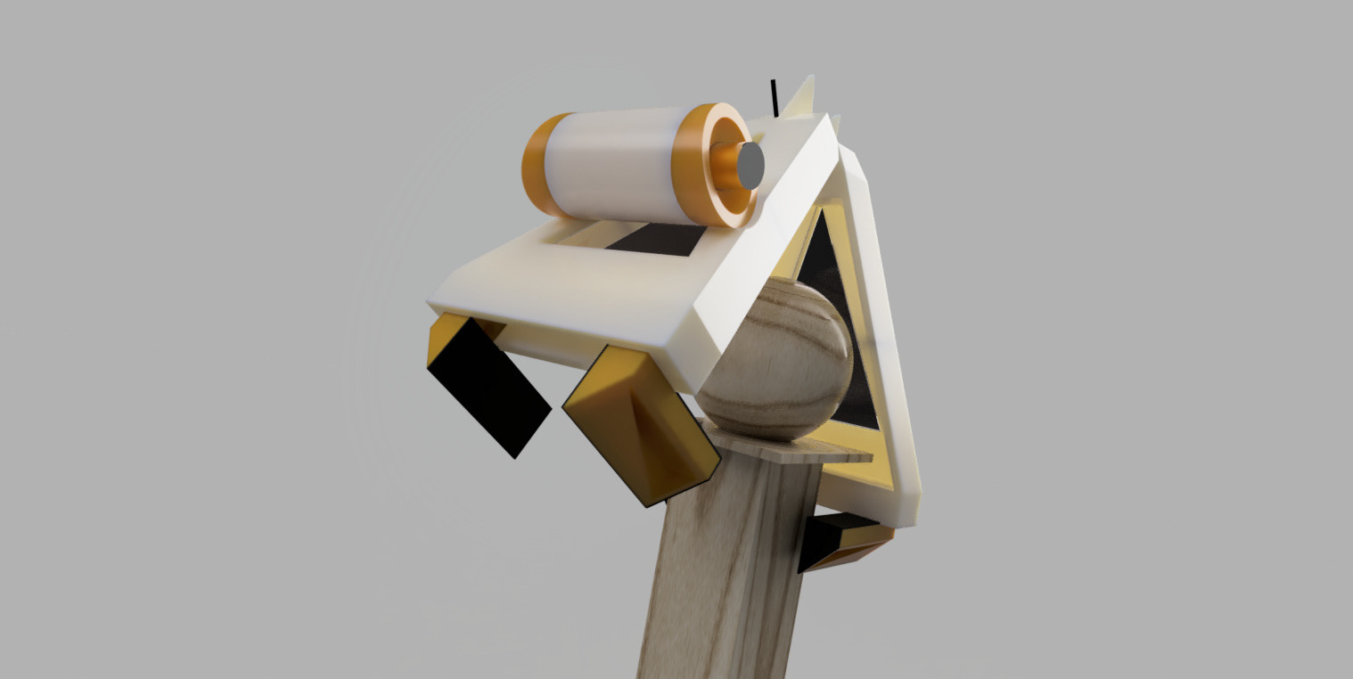
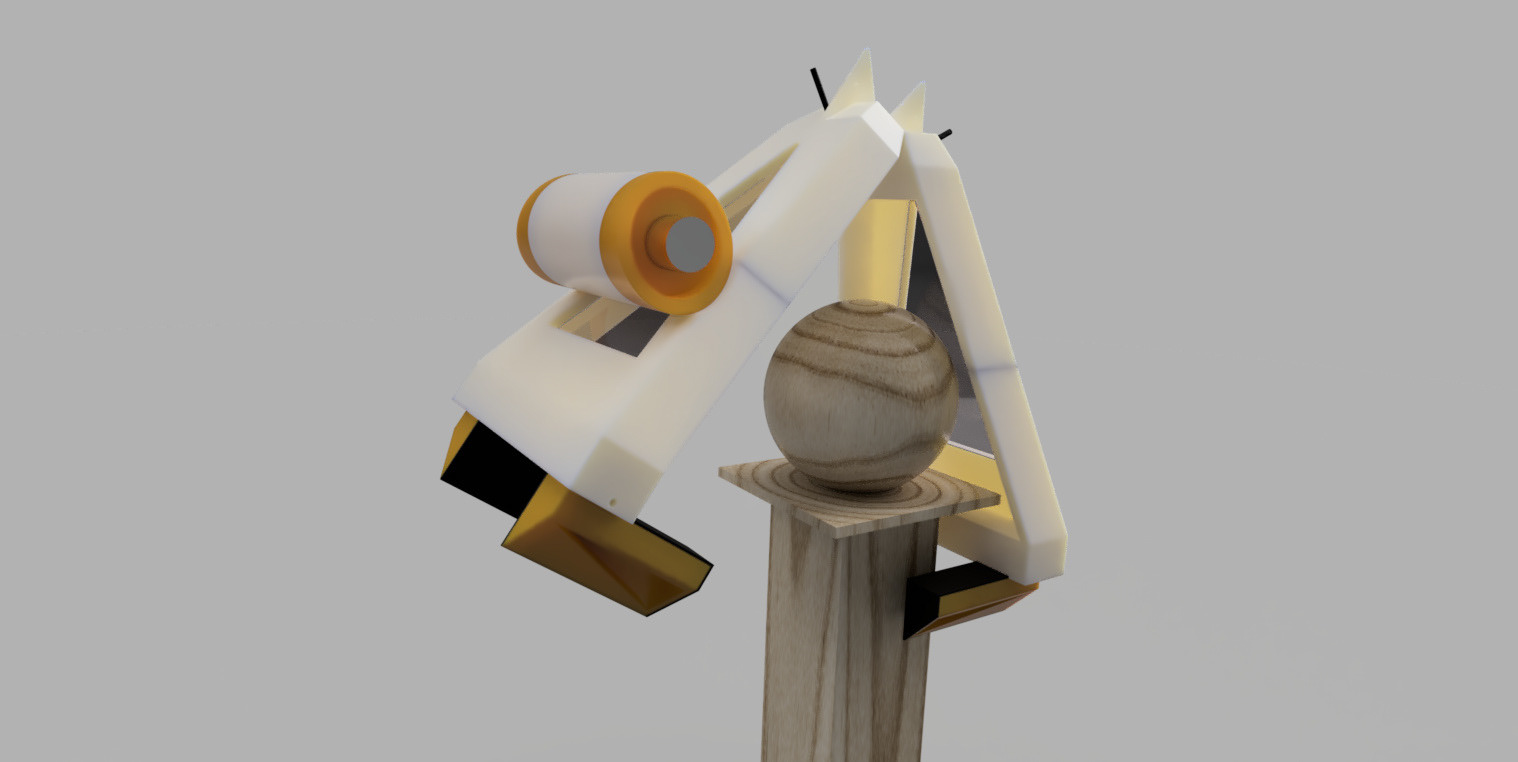
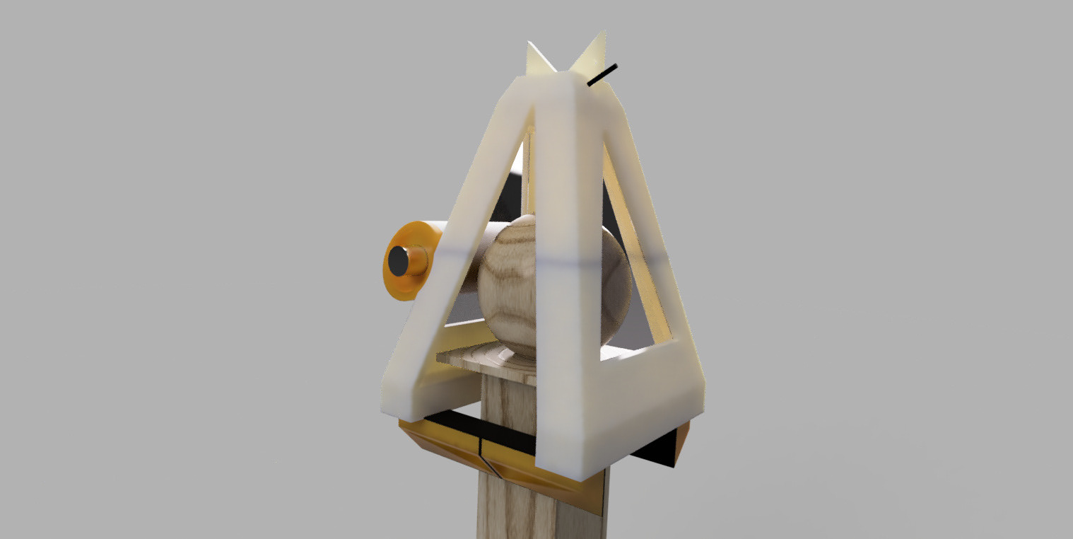
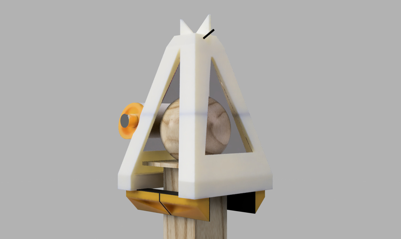
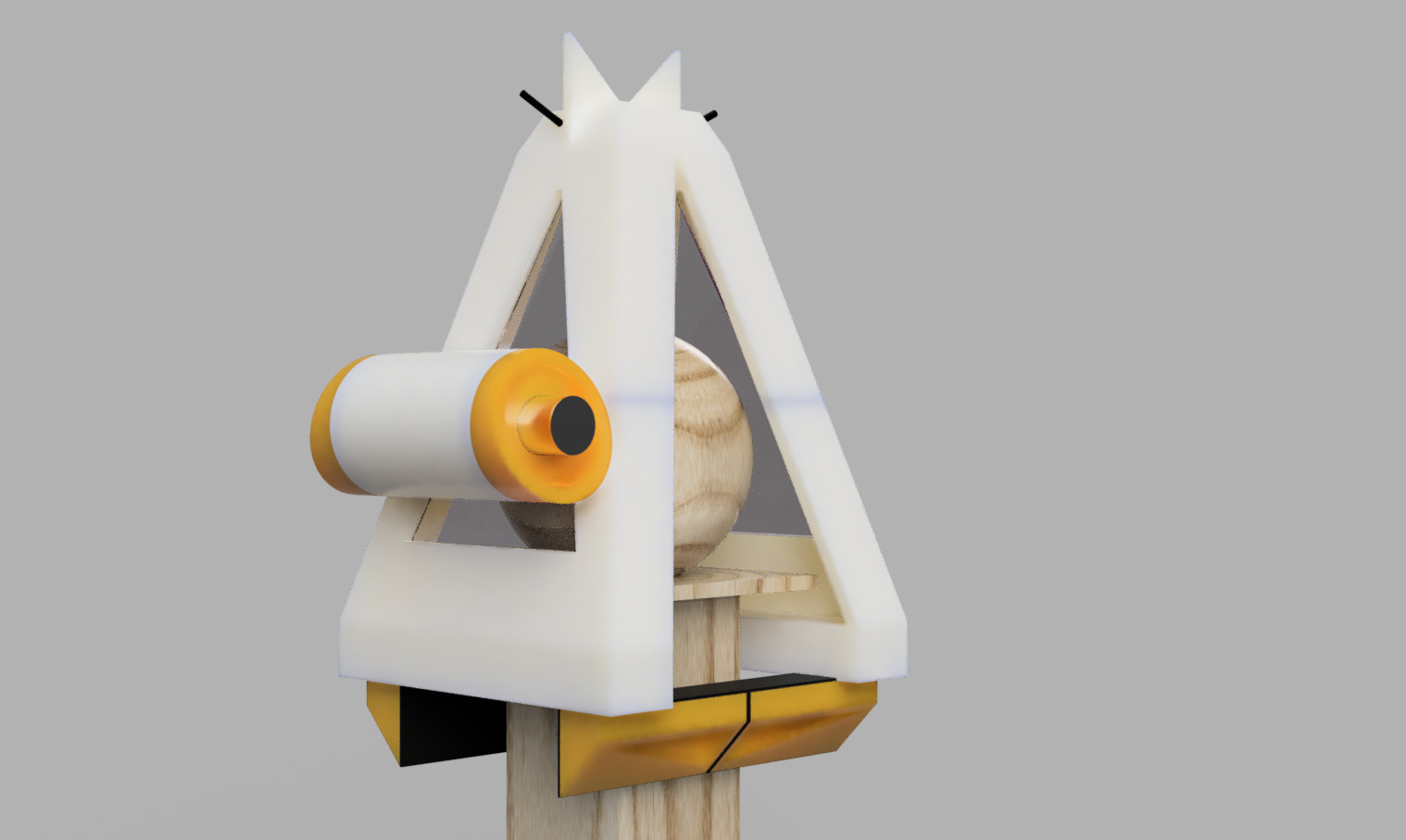
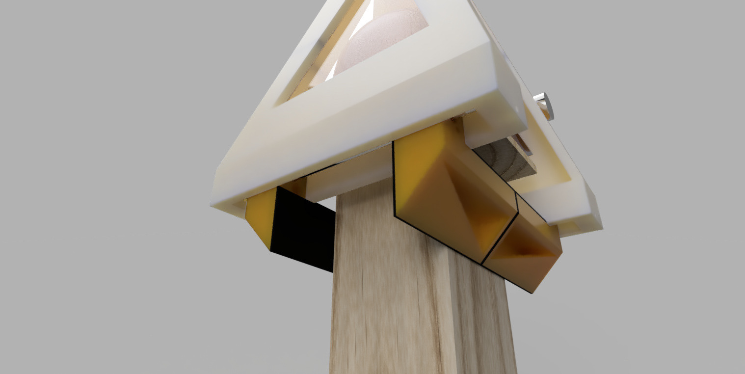
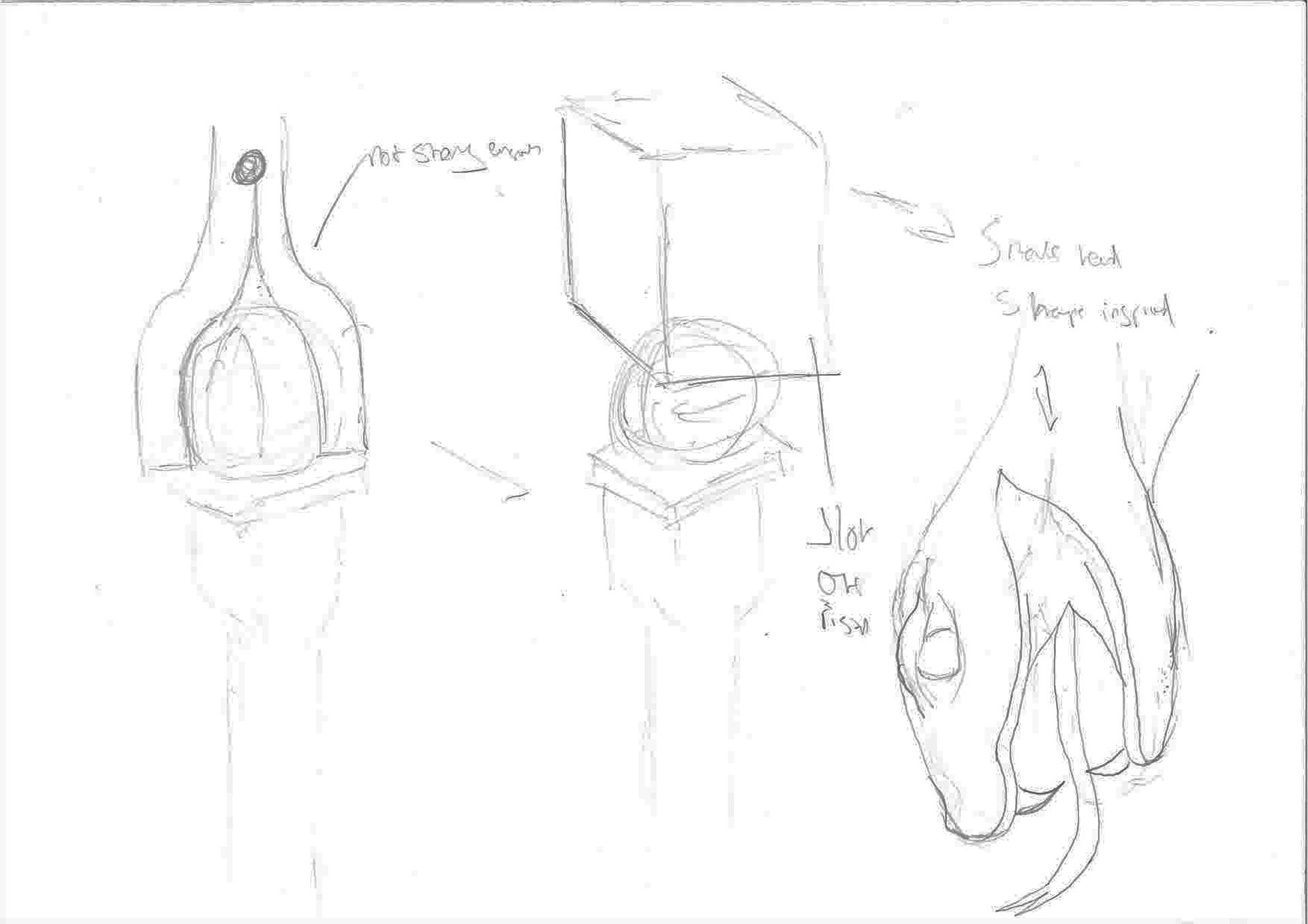
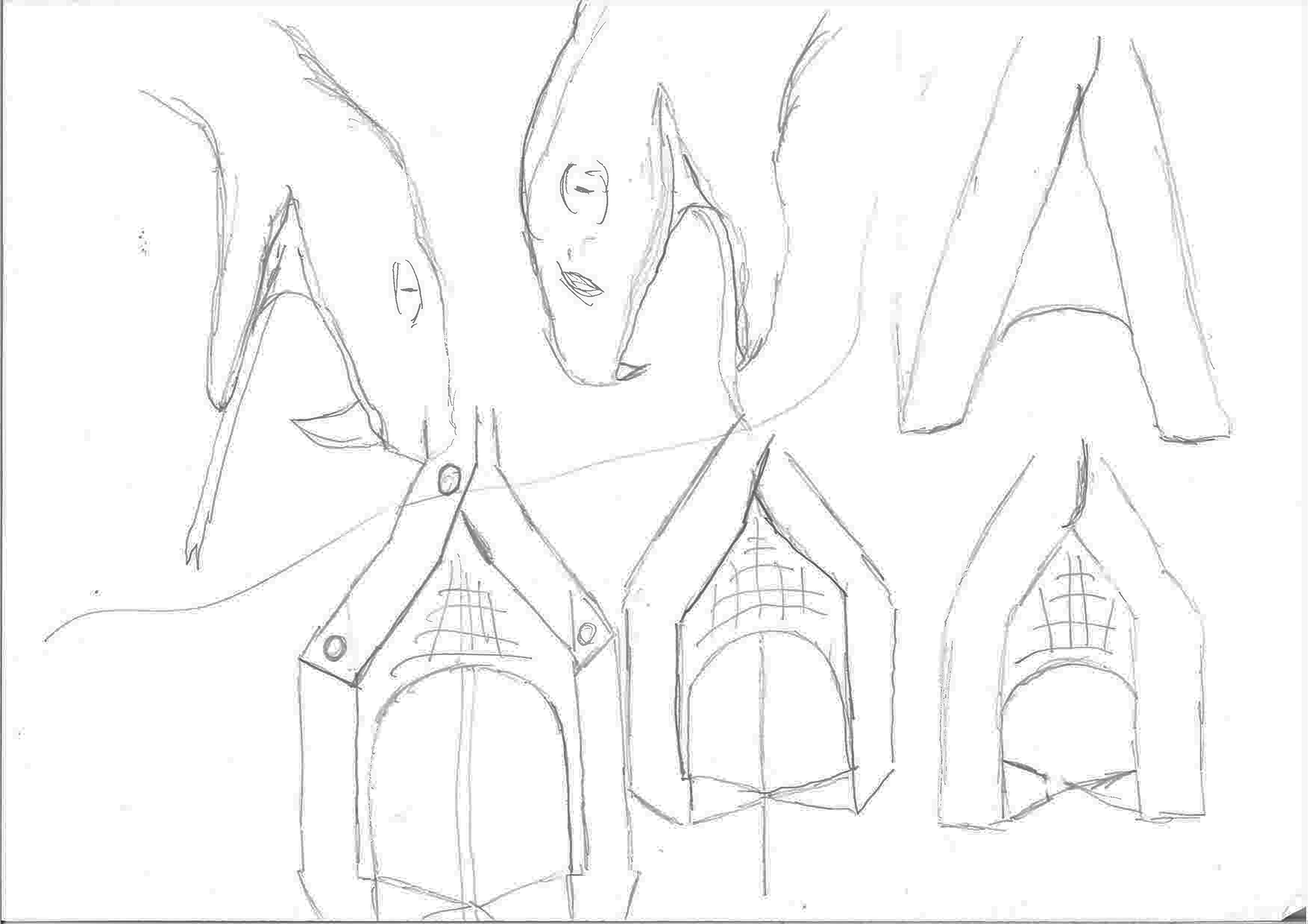
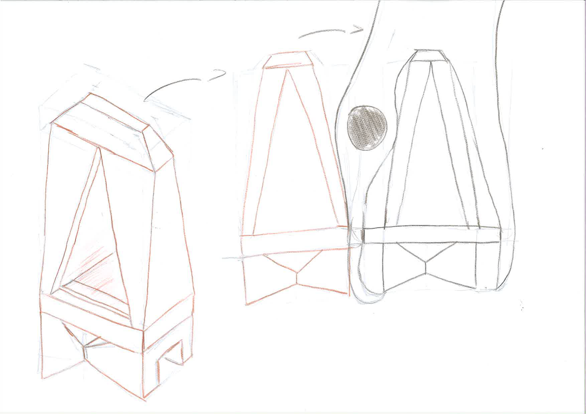
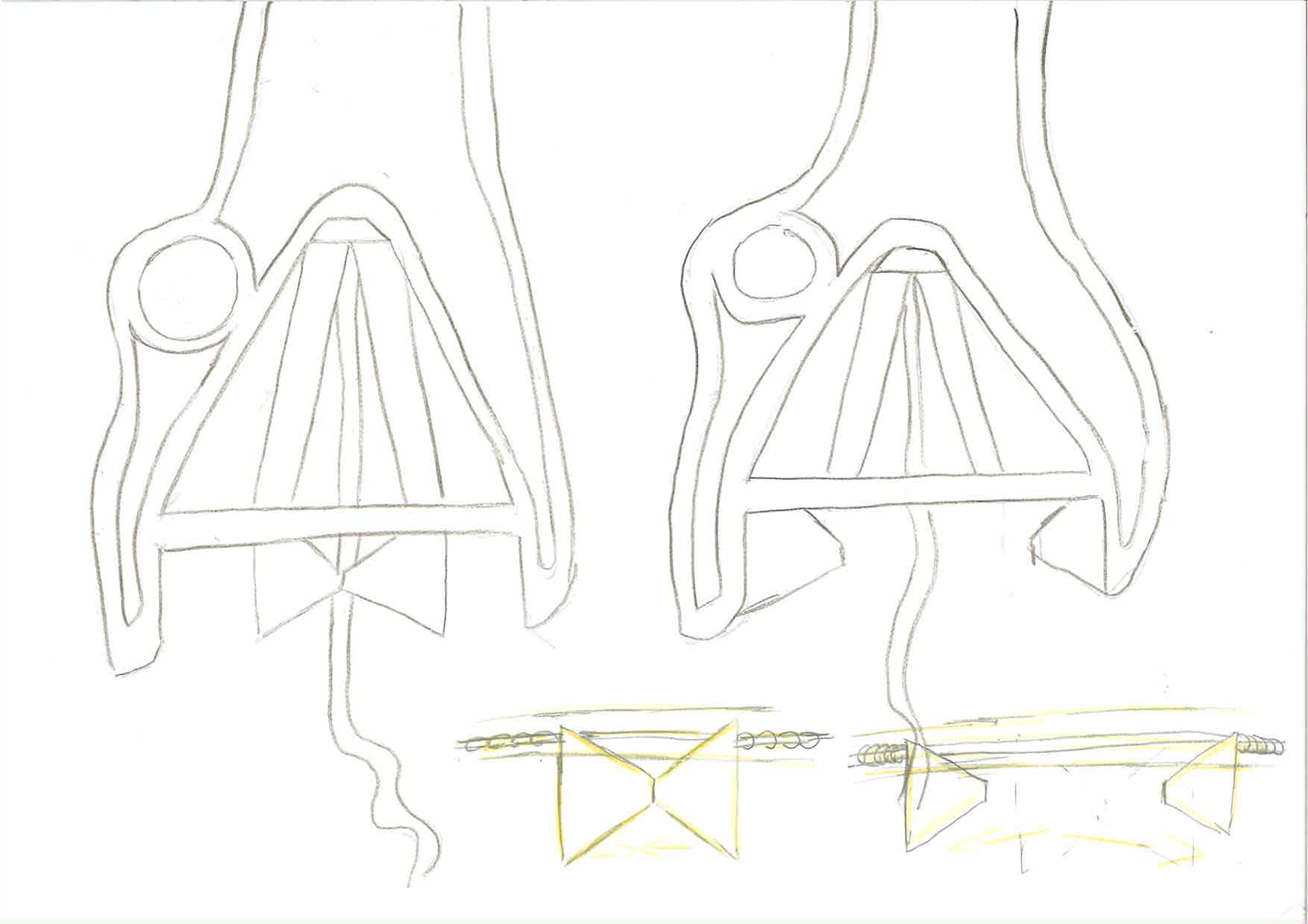
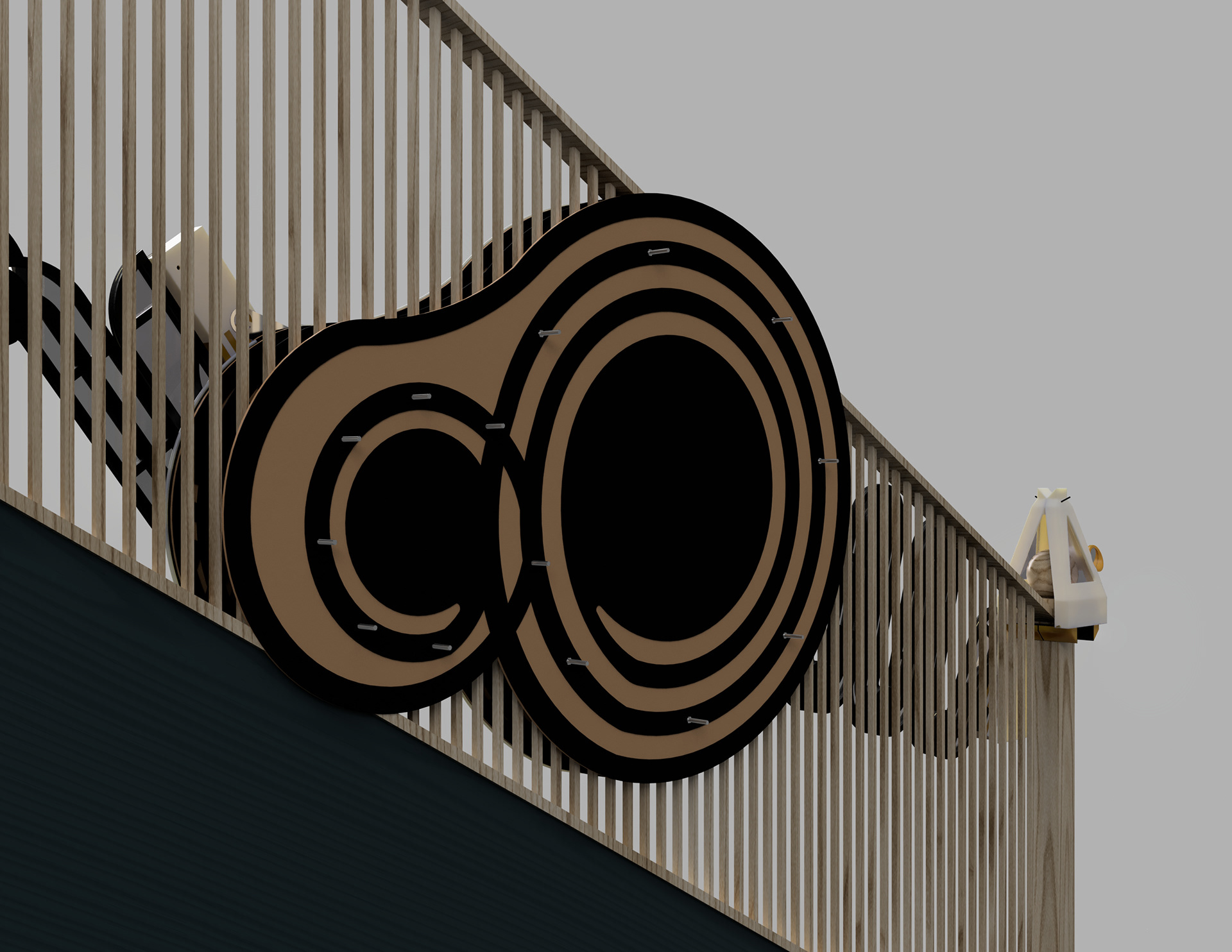
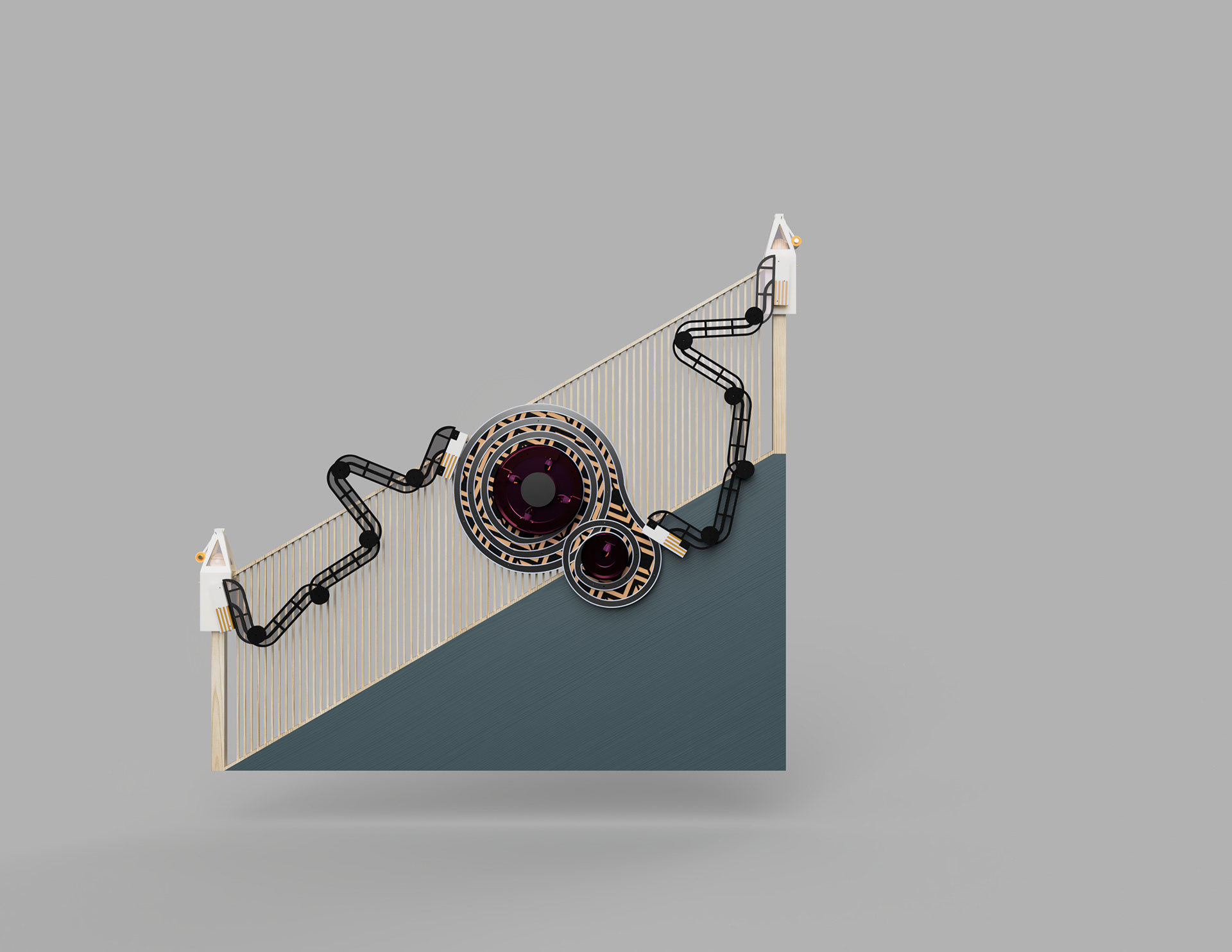
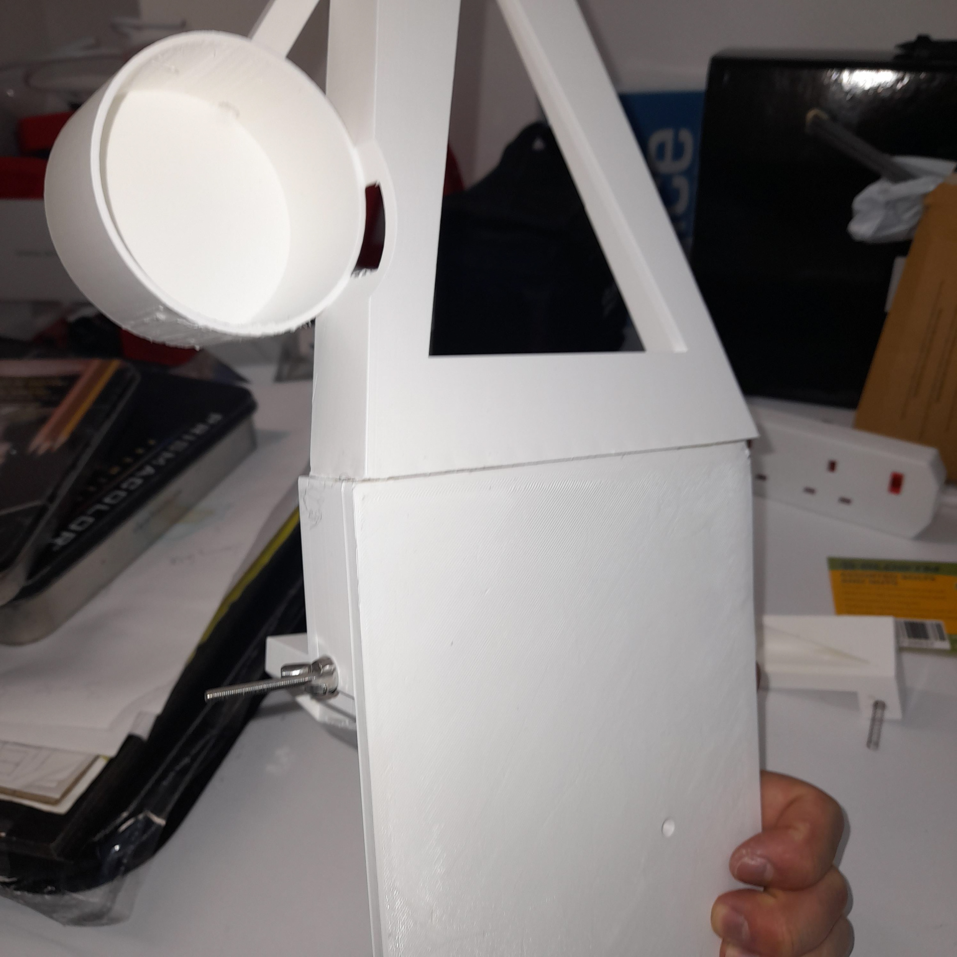
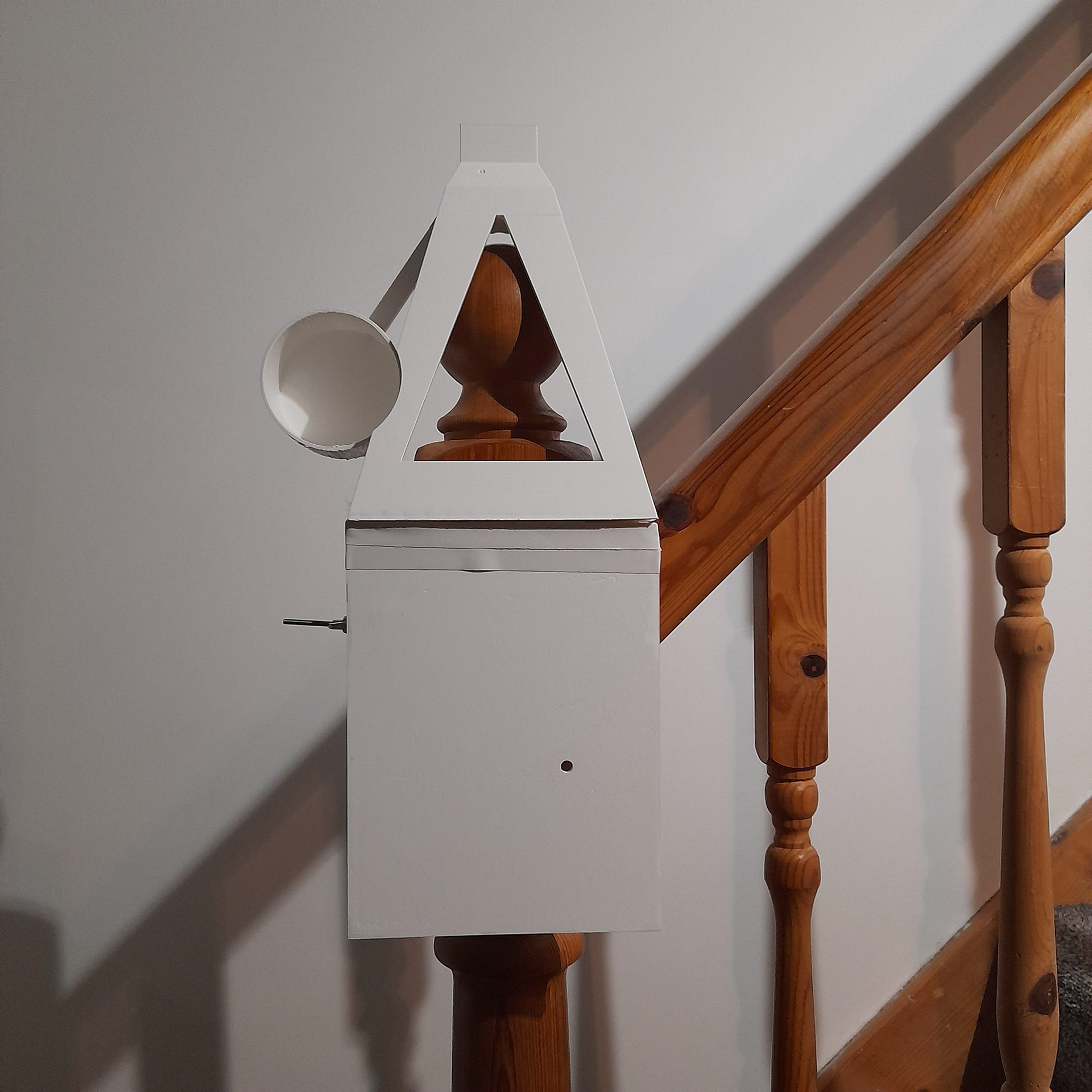
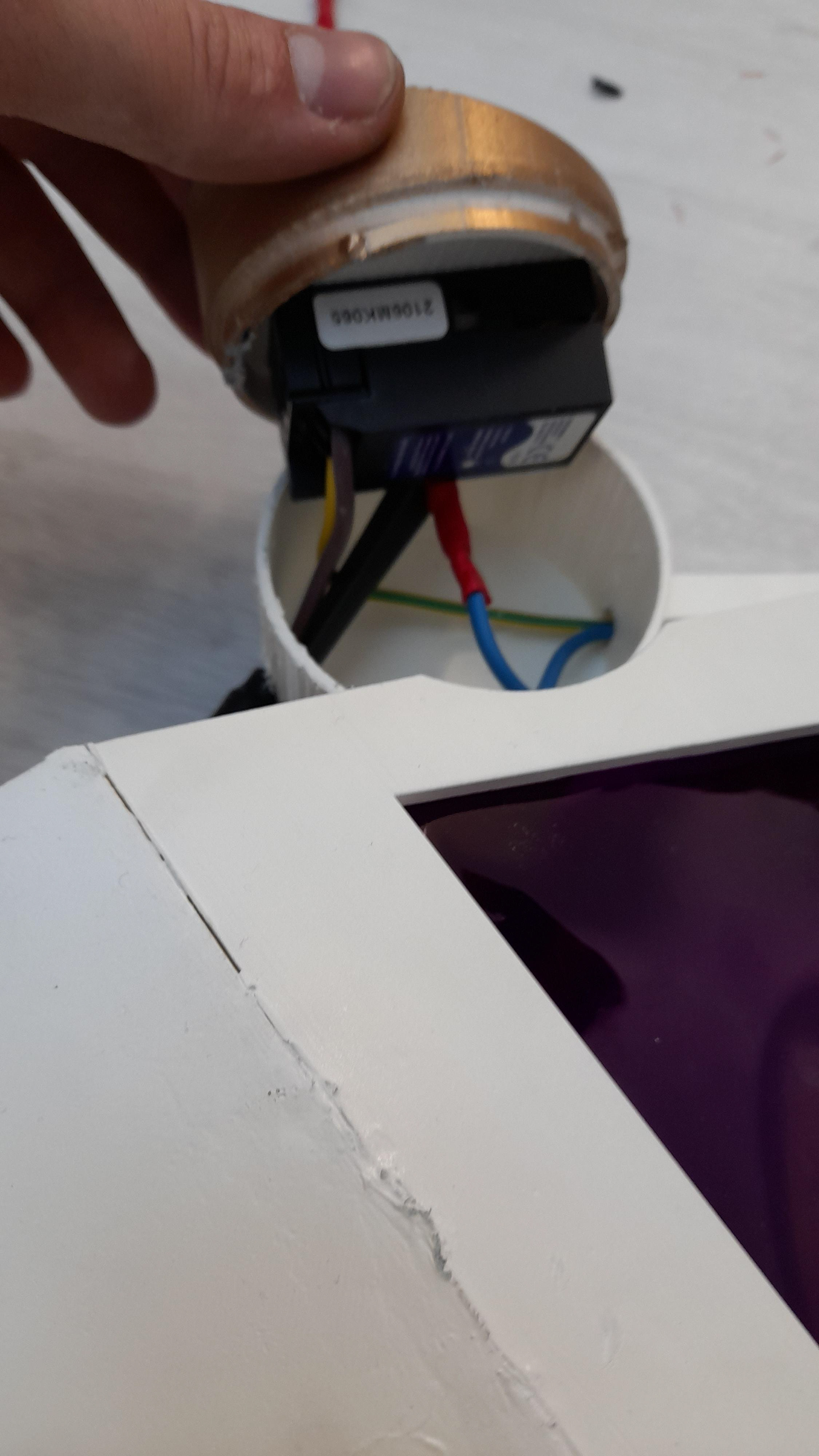
The more render like images above shows the development of the concept. The colours selected match what is already being used in the overall design as in the gold and white. The shape I inspired by a snakehead therefore the eye would be the switch used to turn the light on. However, I intend to use dimmer switches. The reason is in bedknobs & broomsticks (part of the word section), the cap on the end of the bed is twisted and then lights up. I thought it to be suitable to include in my design as well.
The main body o the light is held in place by having a back that would be tightened down by bolts. There again if lets just a person didn't want the bolts sticking out then they could just drill and screw it in place instead. The reason being once it is been positioned on the stairs it is unlikely the person is going to change its position again.
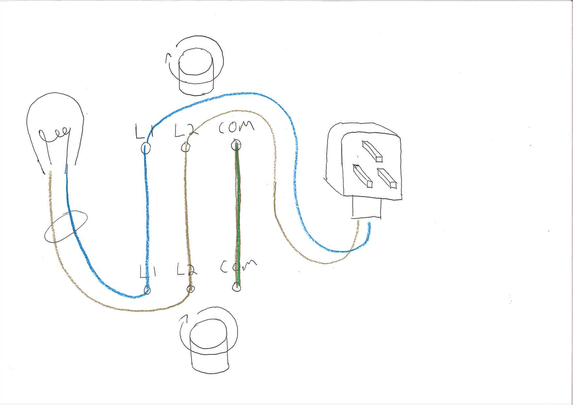
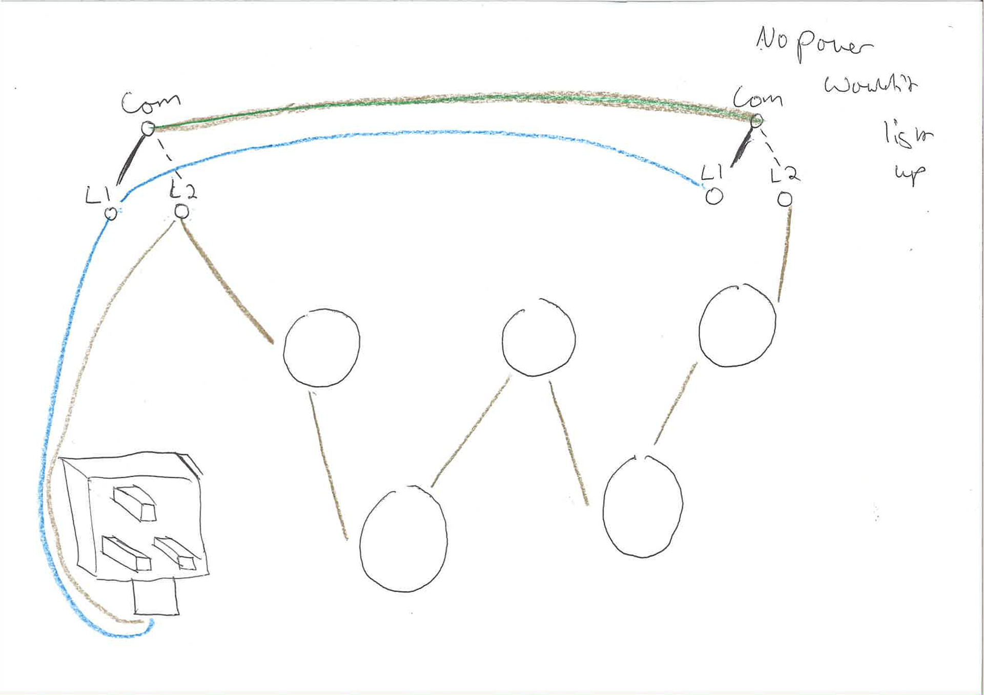
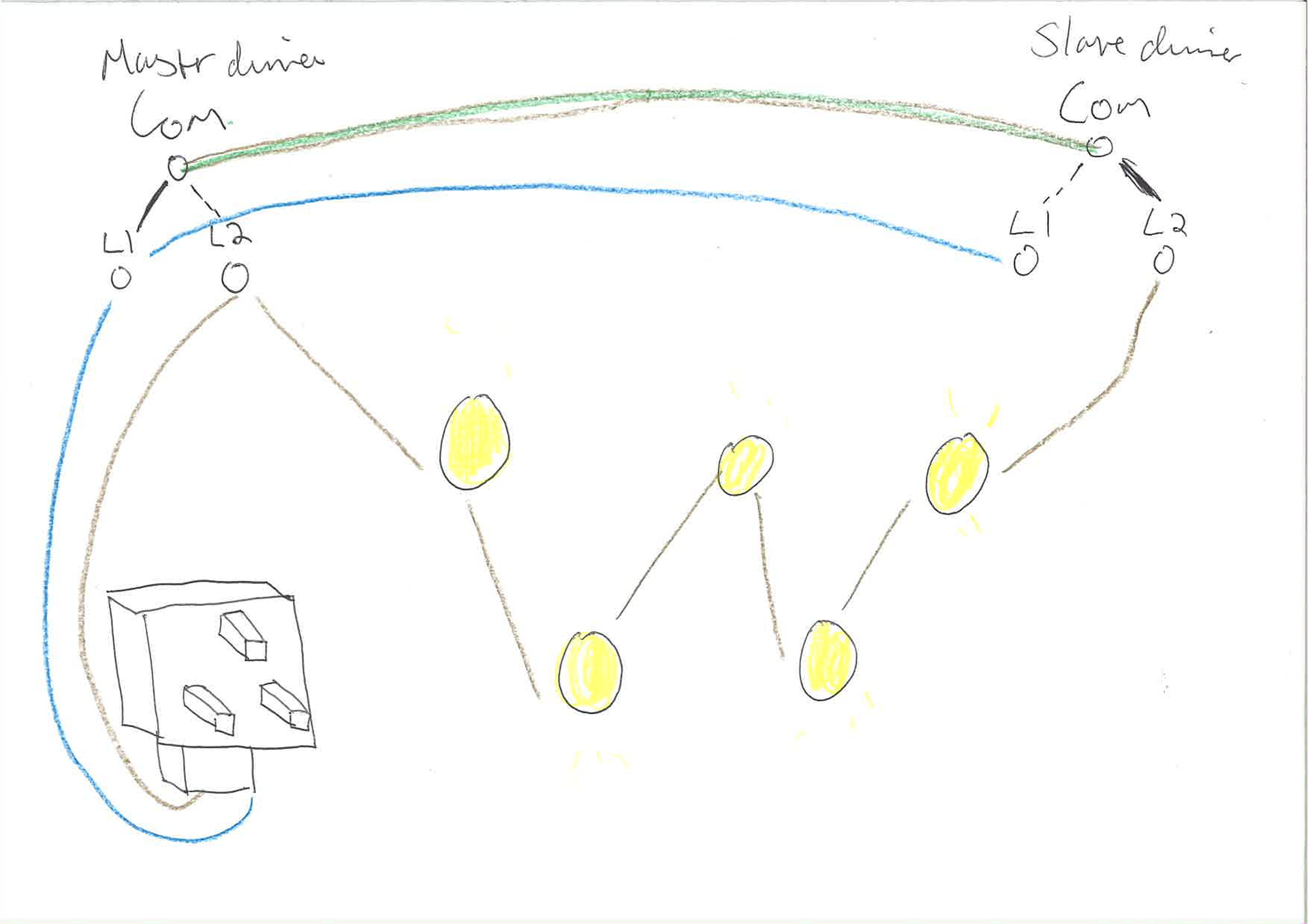
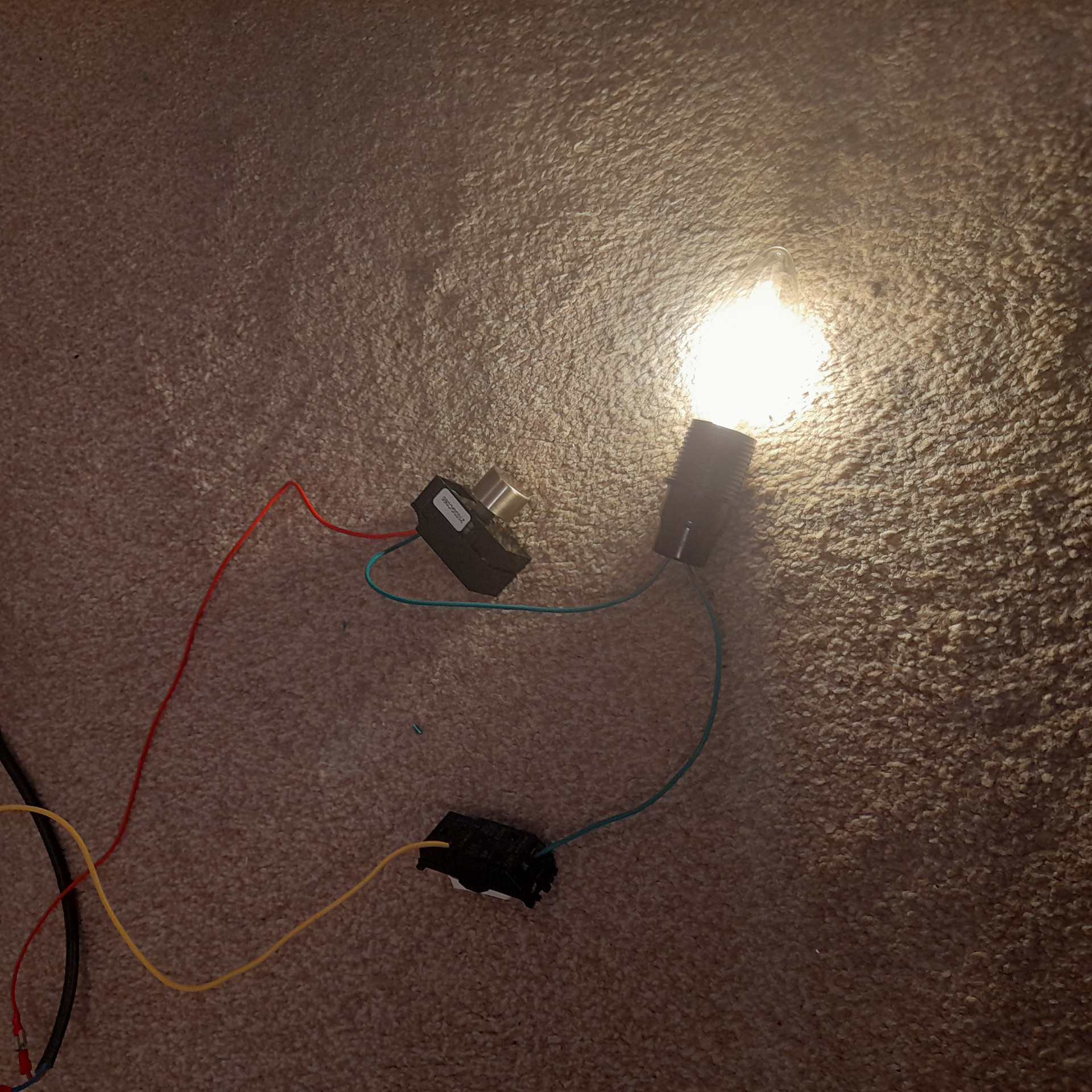
Although I'm pretty confident in wiring this light-up ( due to previous projects), I still thought it would be worth my while trying out a few combinations. Because of this, I realised that the light couldn't have two dimmer switches even if it were master and slave type. The reason is they don't completely turn off. Hence instead there will be one dimmer (1 gang 2 way) and a regular wall switch ( 1 gang 2 way). The dimmer will be located on the bottom clamp and the regular on the top. The reason is it is unlikely you are going to care about the light if you are above it since the glare wouldn't affect you. Whereas below it would.
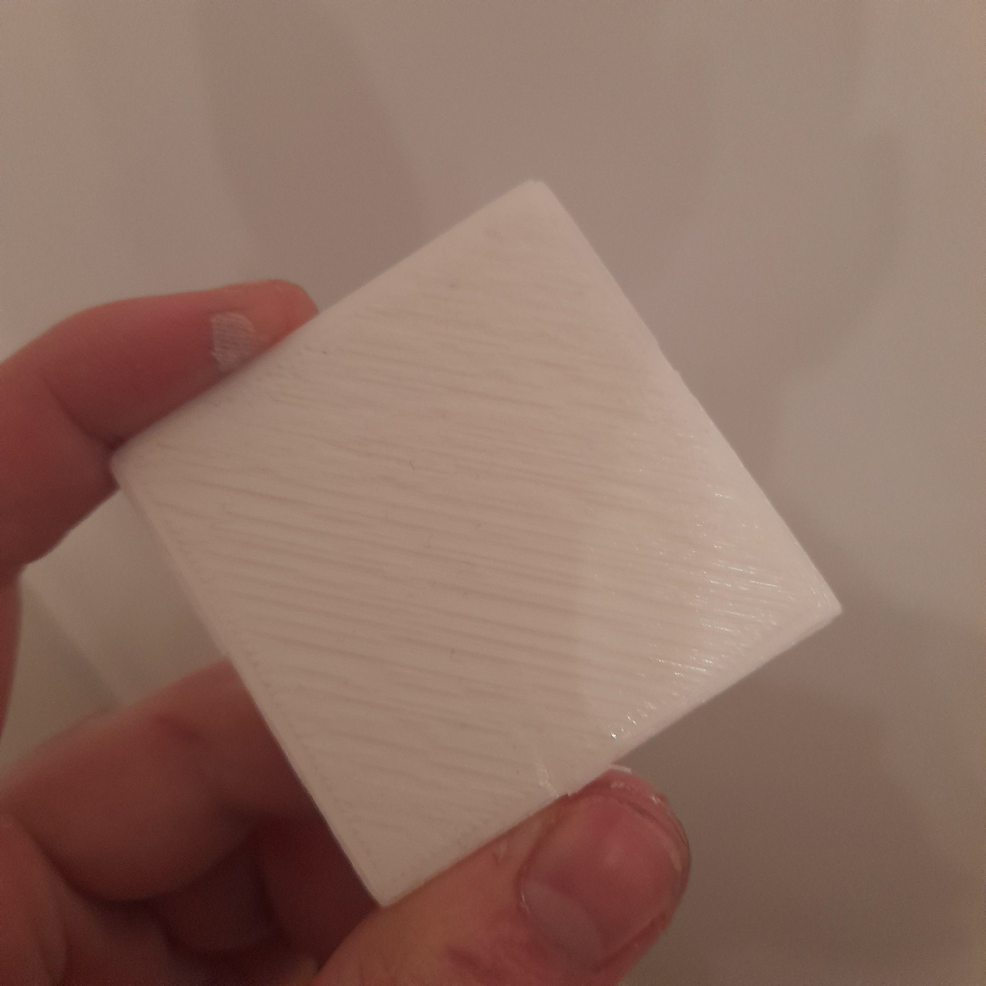
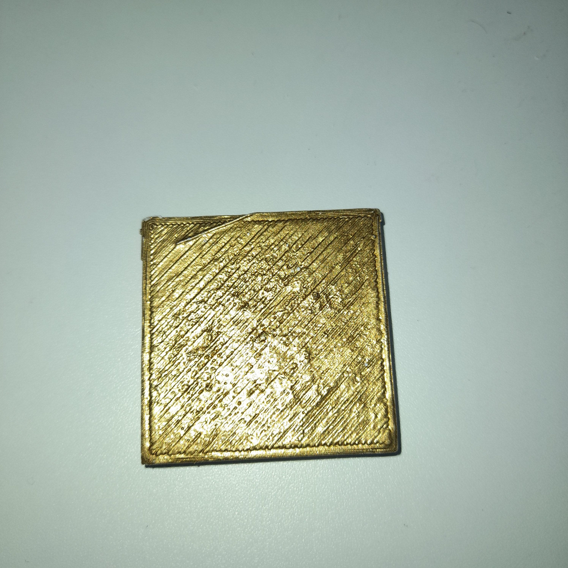
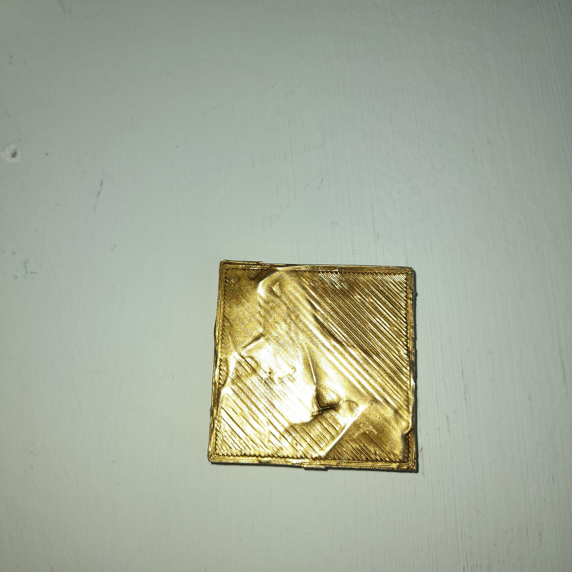
Considering that there is a recurring issue with the tidiness of the 3d printed parts. ( i wanted to try out different surface techniques. The two I tried were primer spray paint and gesso and spray paint.
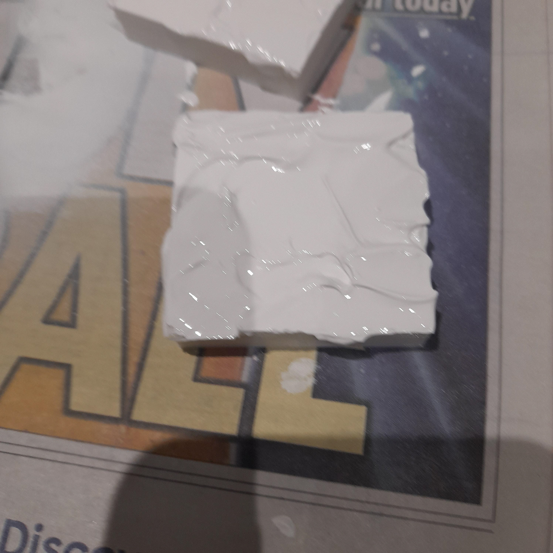
Then I thought why not combine both. the outcome of this does give an interesting visual look. However, this is not going to be suitable for every part.
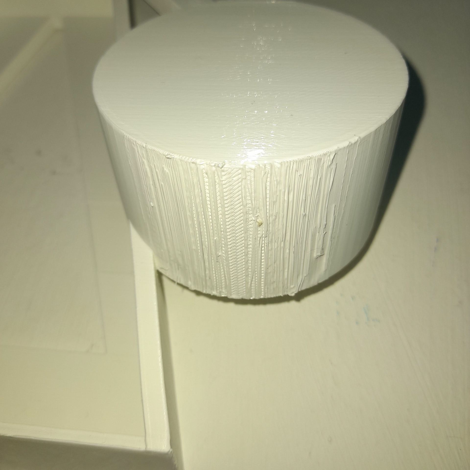
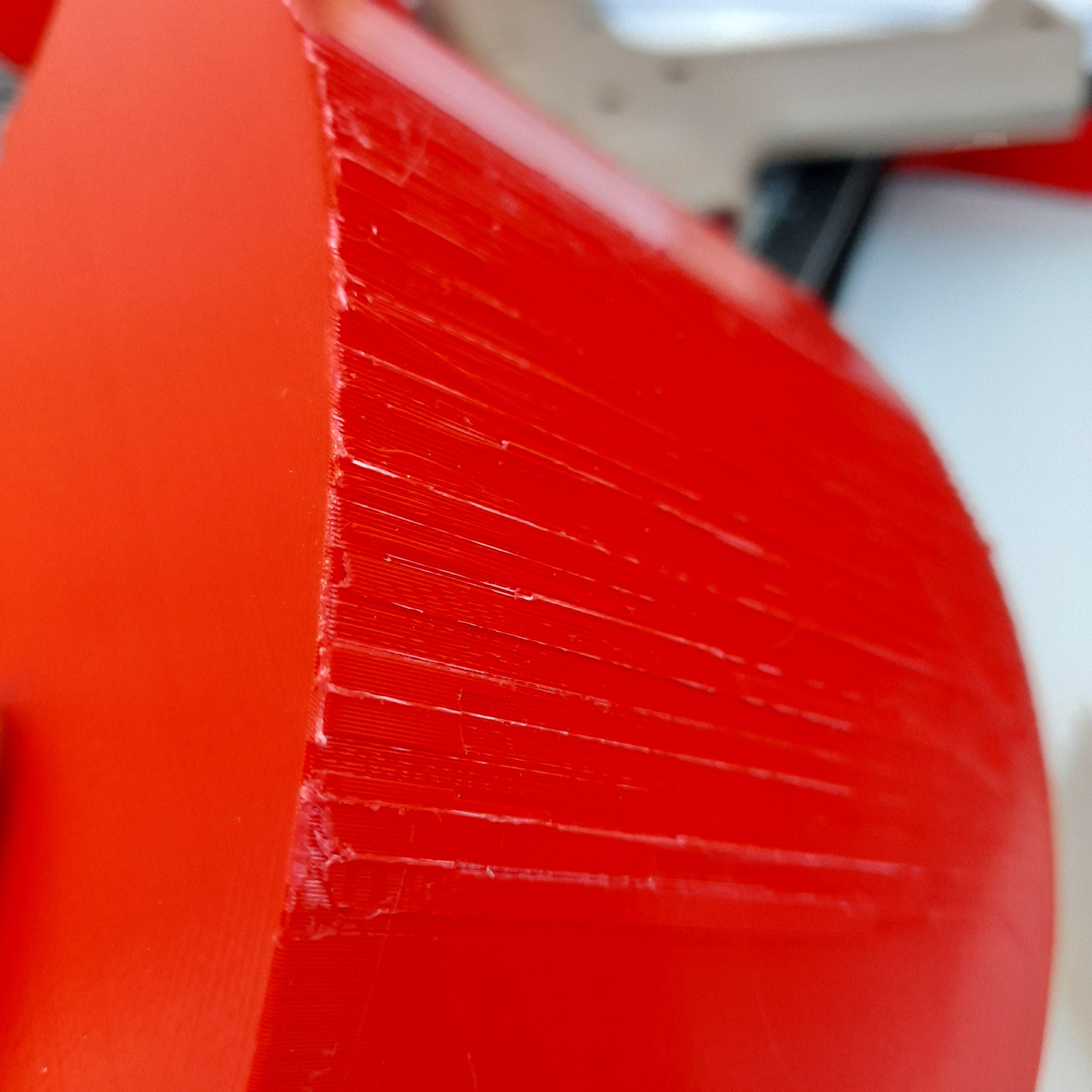
For example, you can see how the outer layers in the above-printed model are rough. Hence I will the gesso and primer mix.
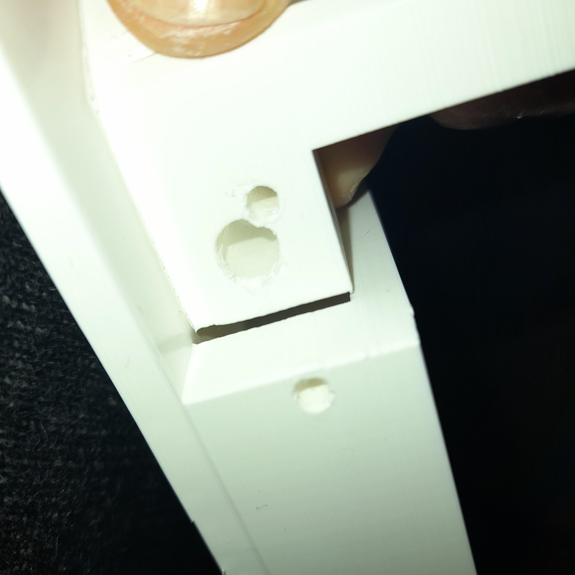
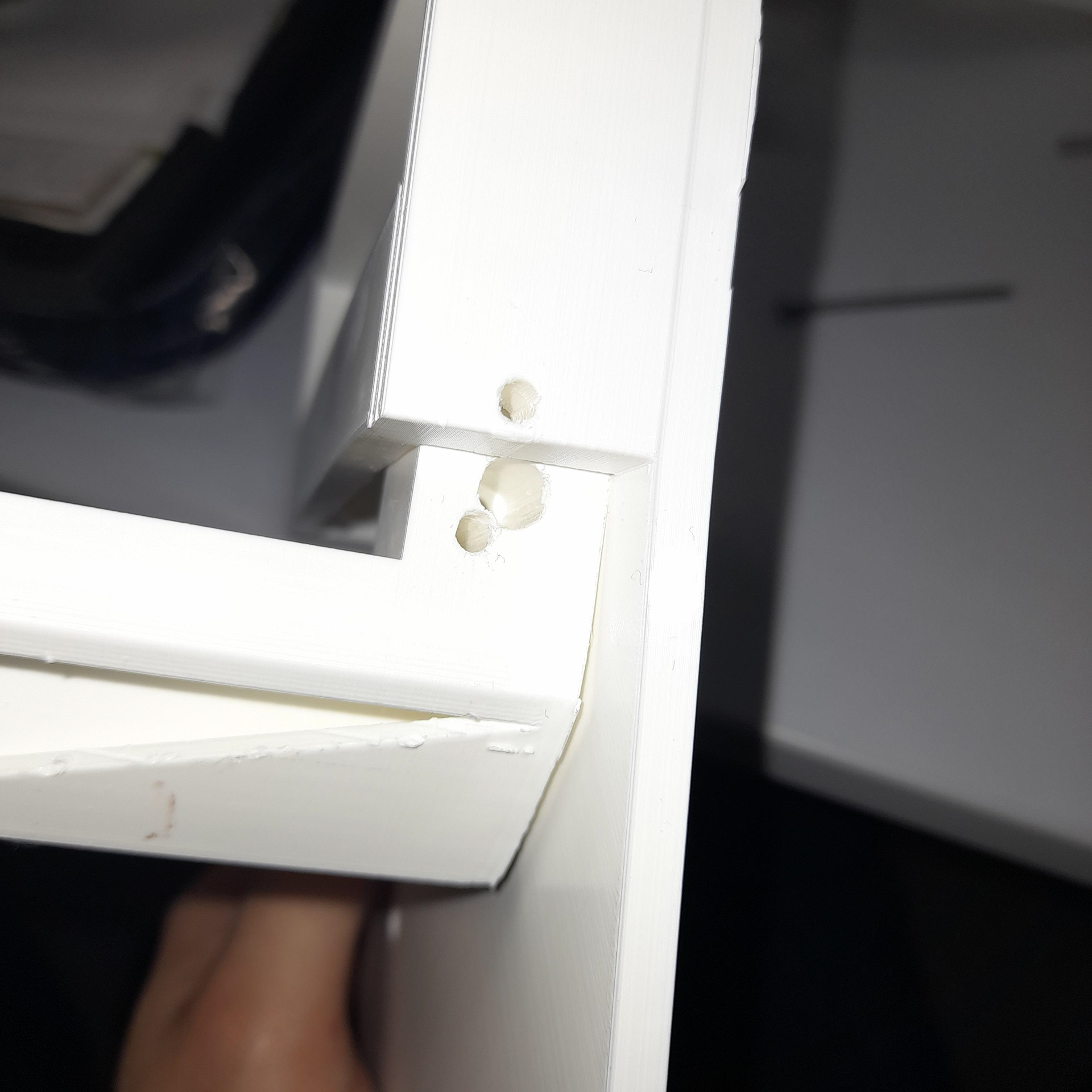
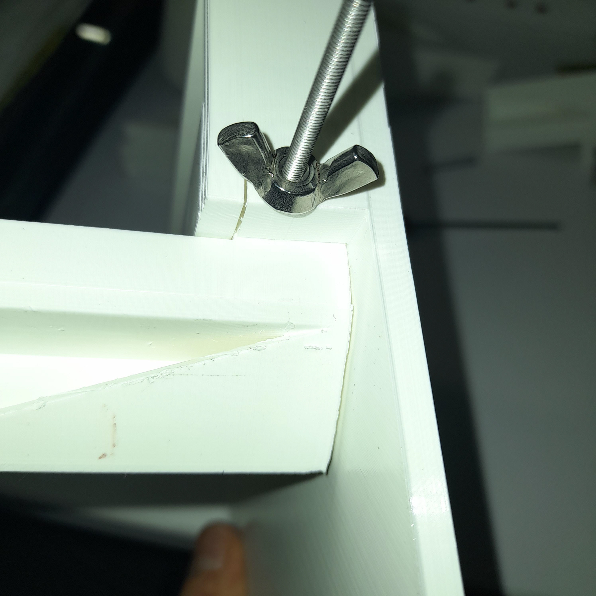
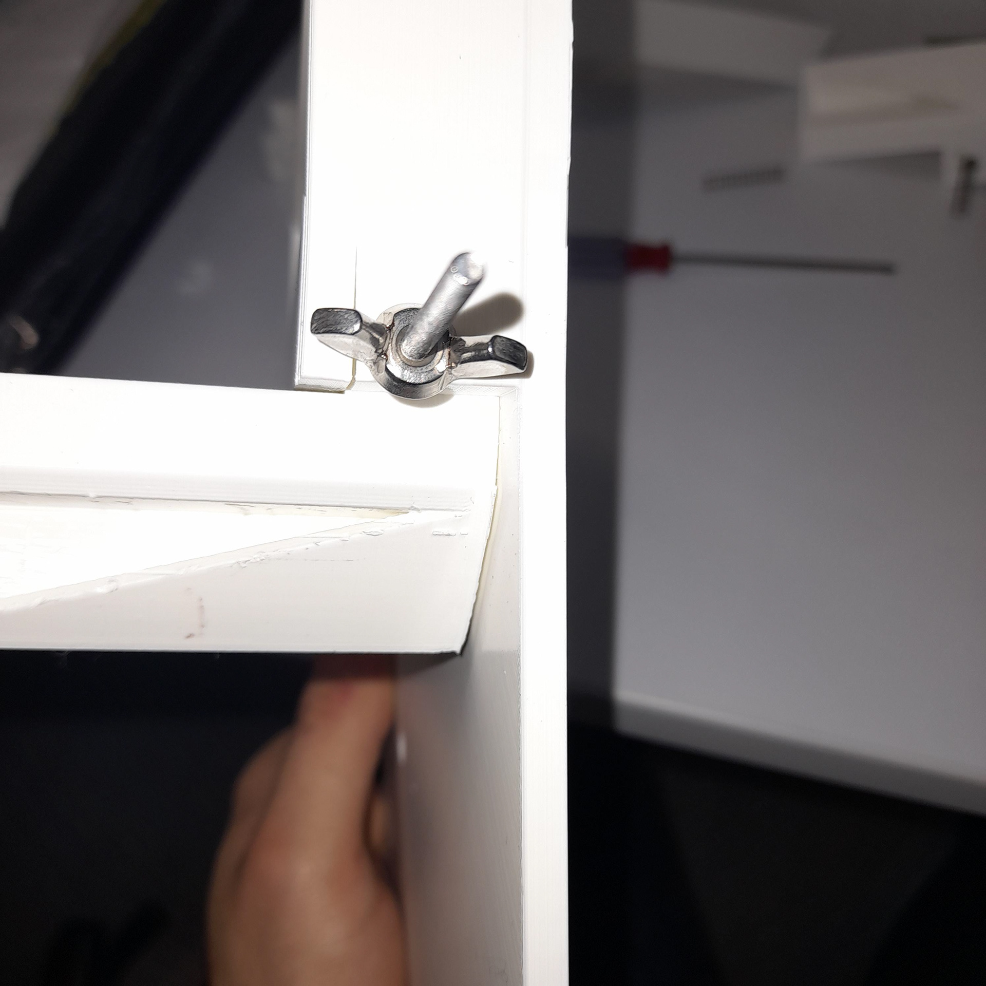
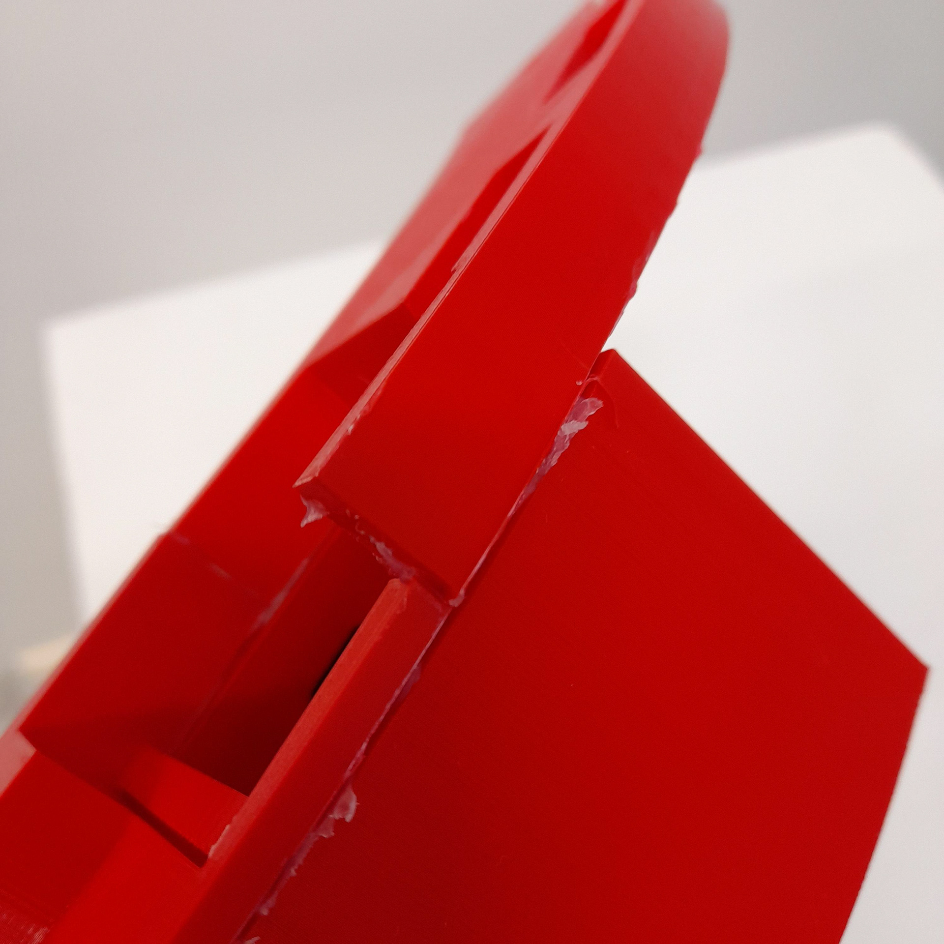
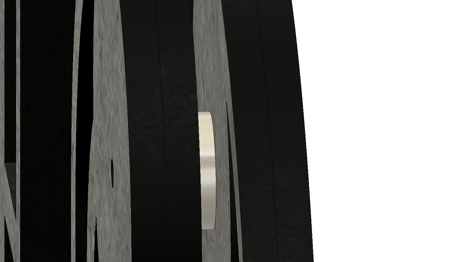
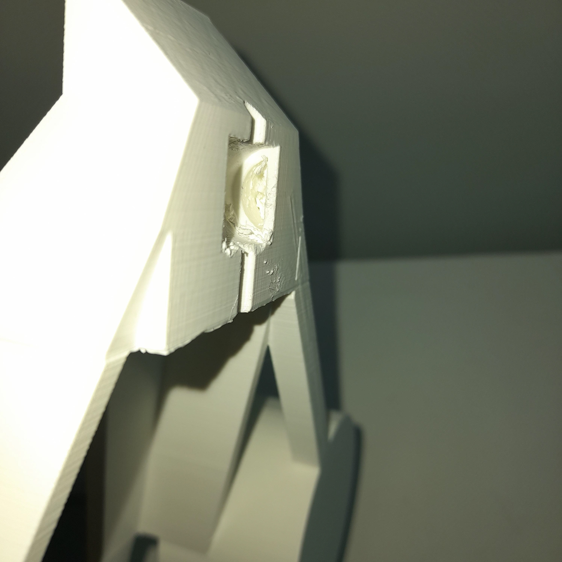
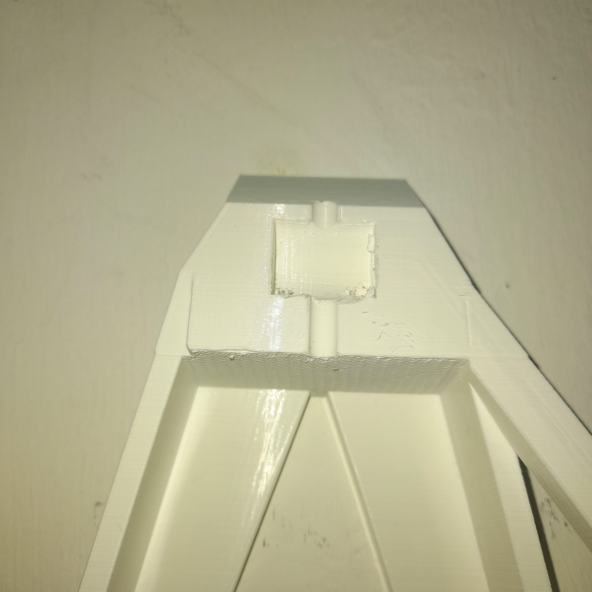
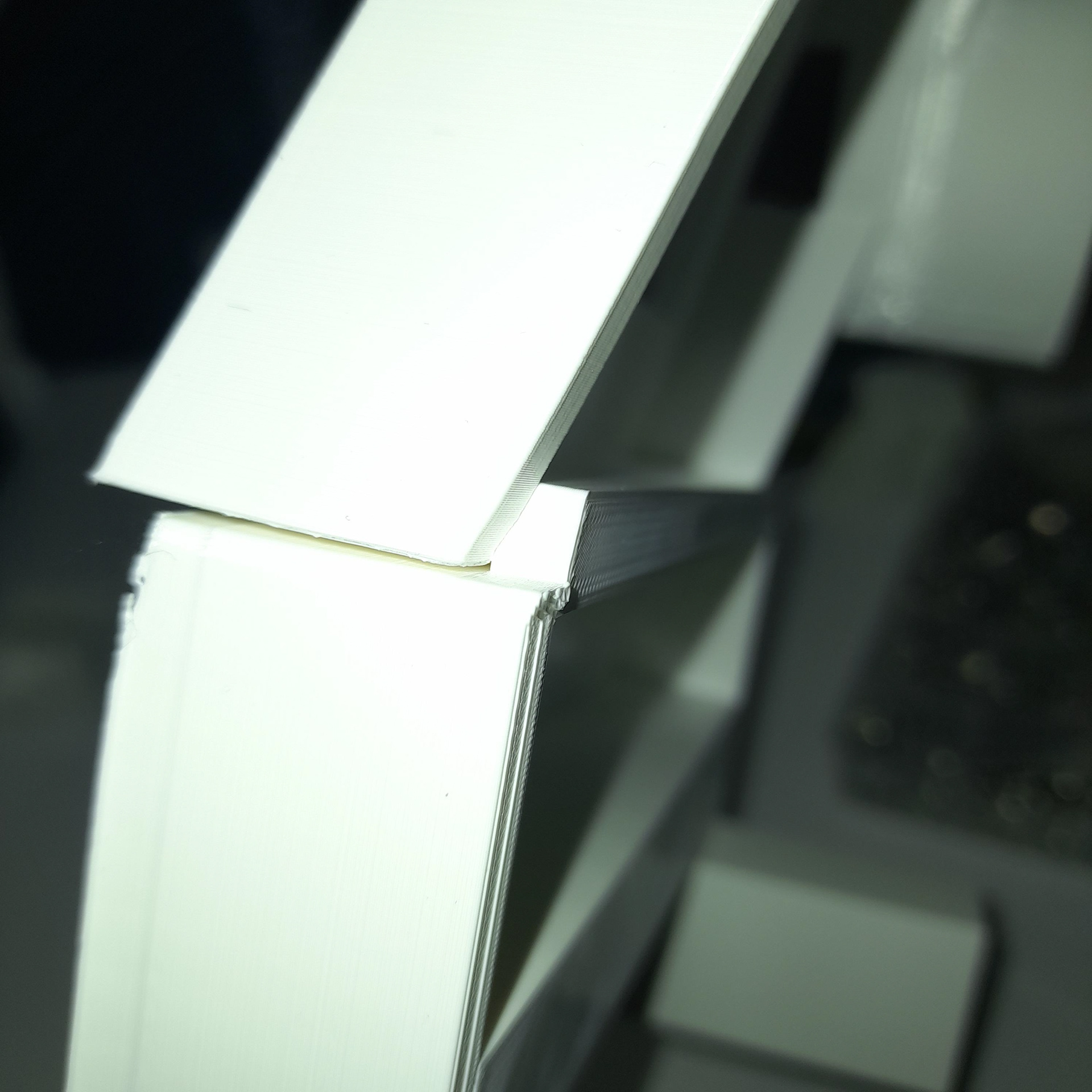
Before printing the final part, I needed to do numerous trial pieces to figure out what adjustments were needed. As you can see there are cracks that can occur when firring parts together.
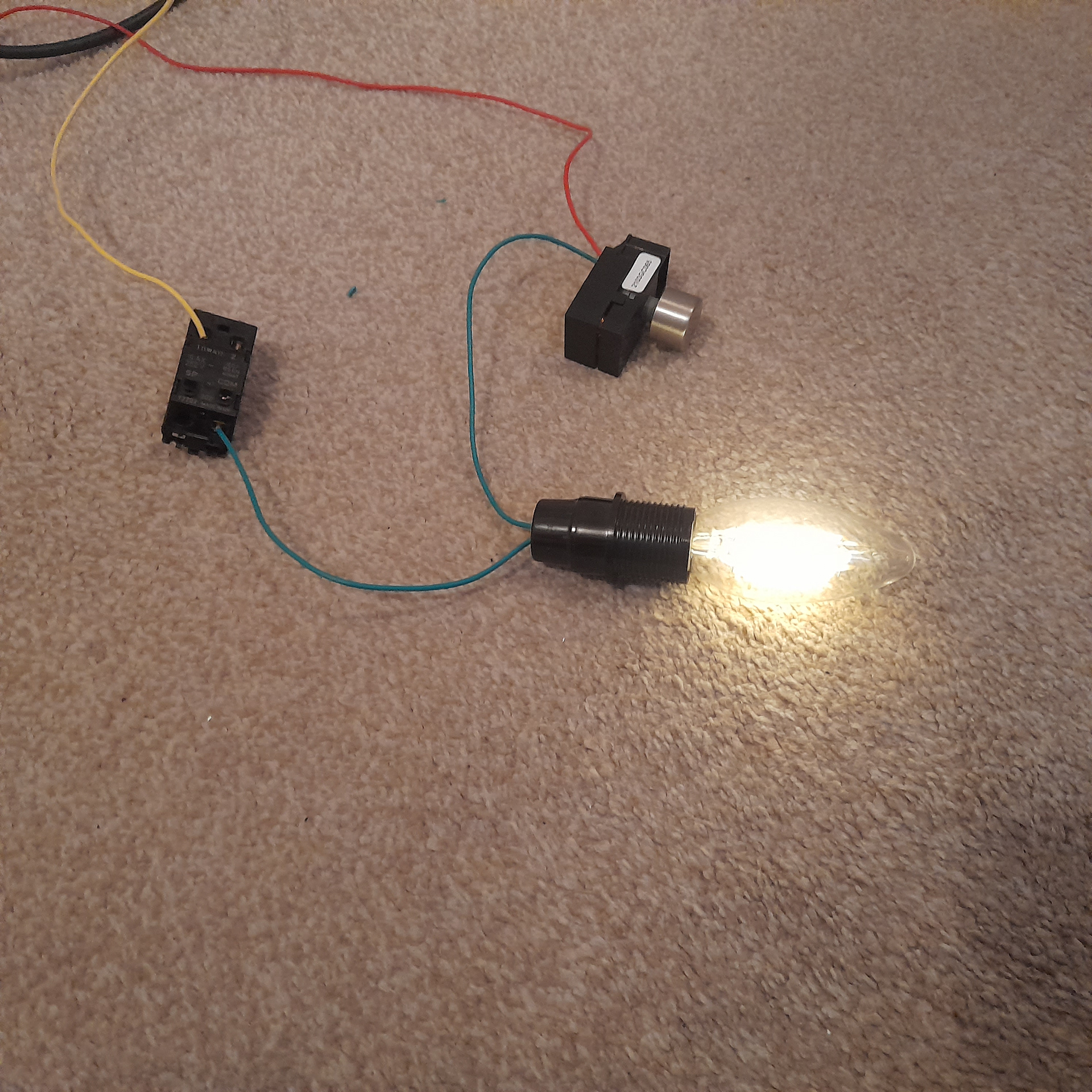
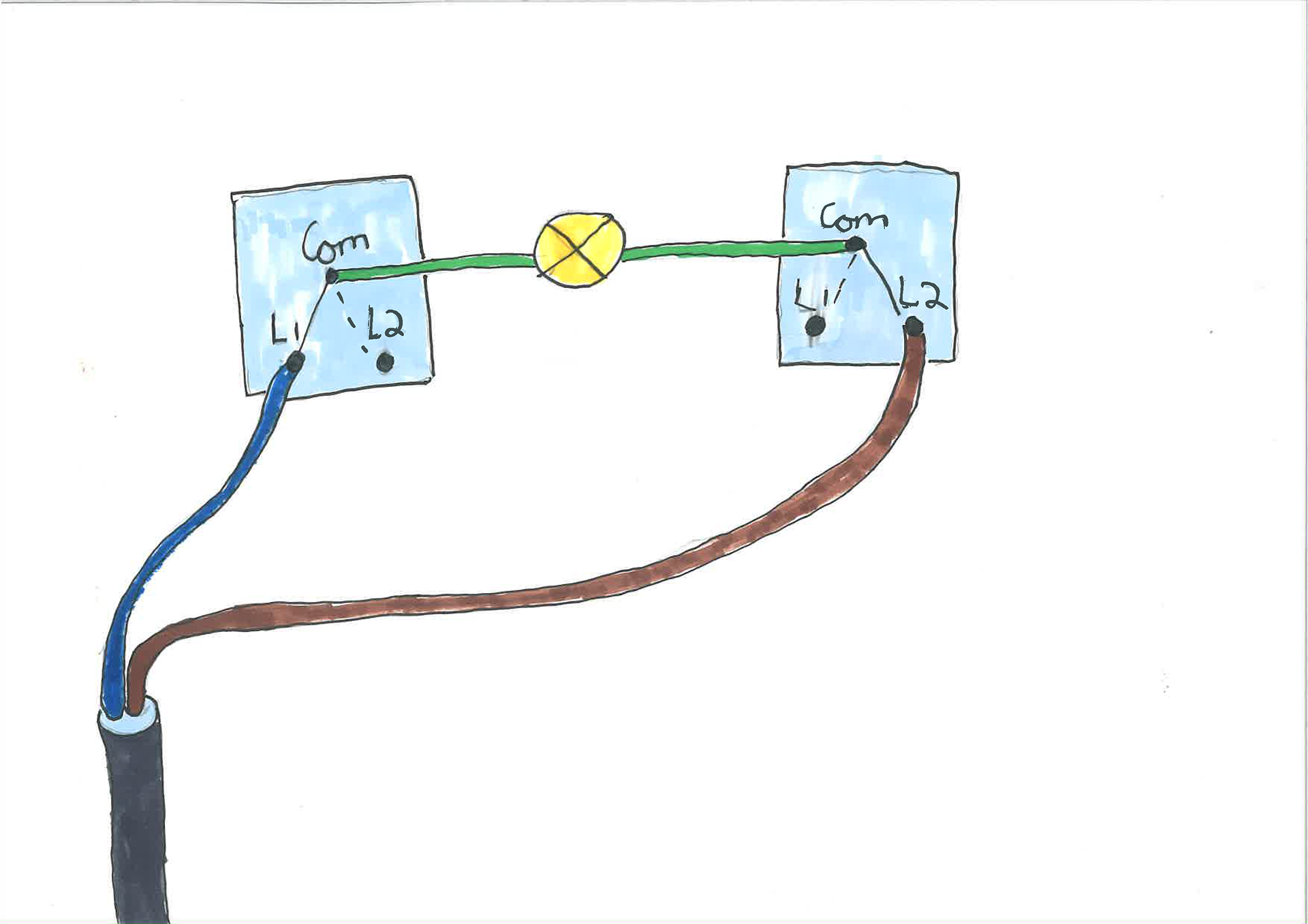
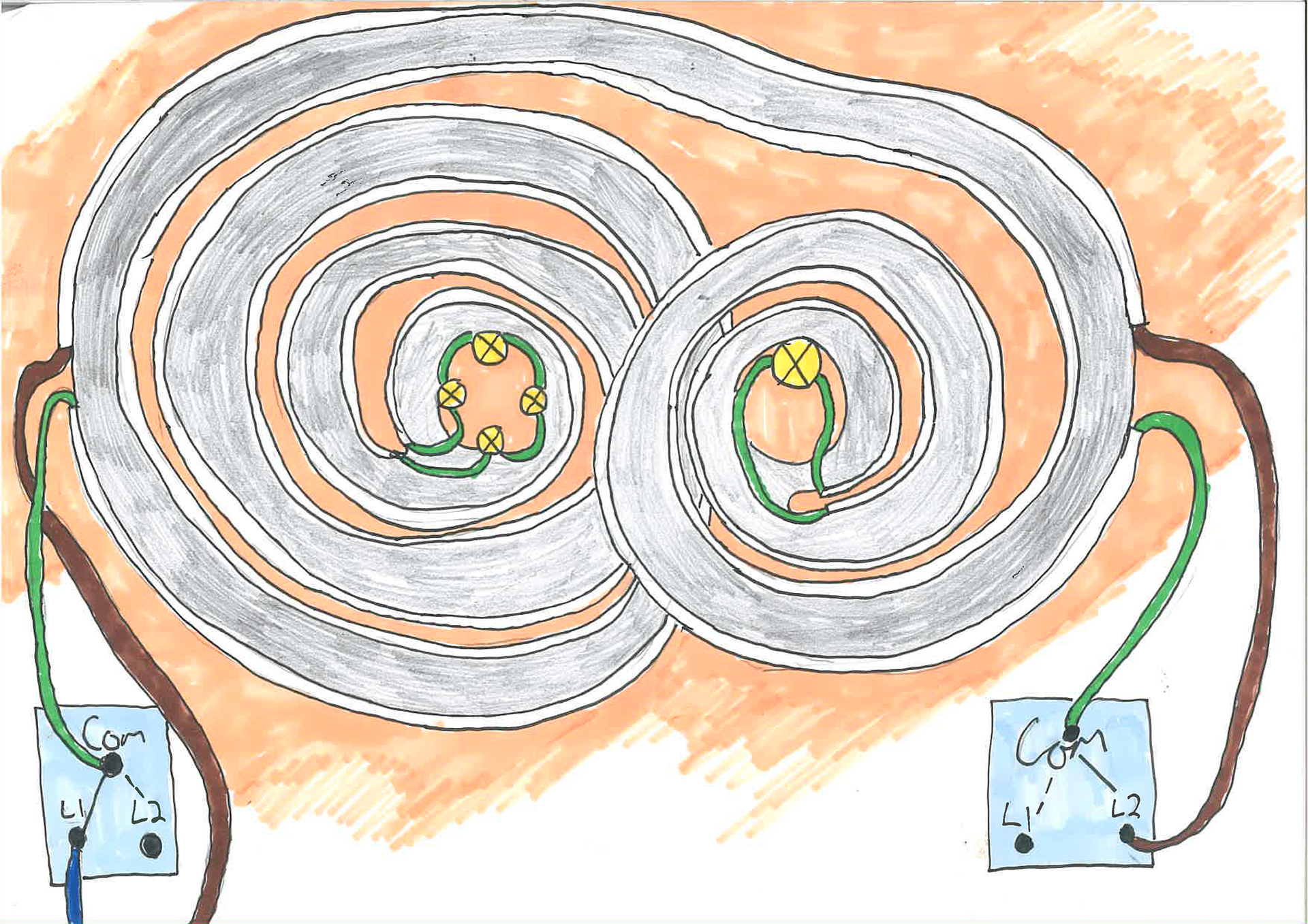
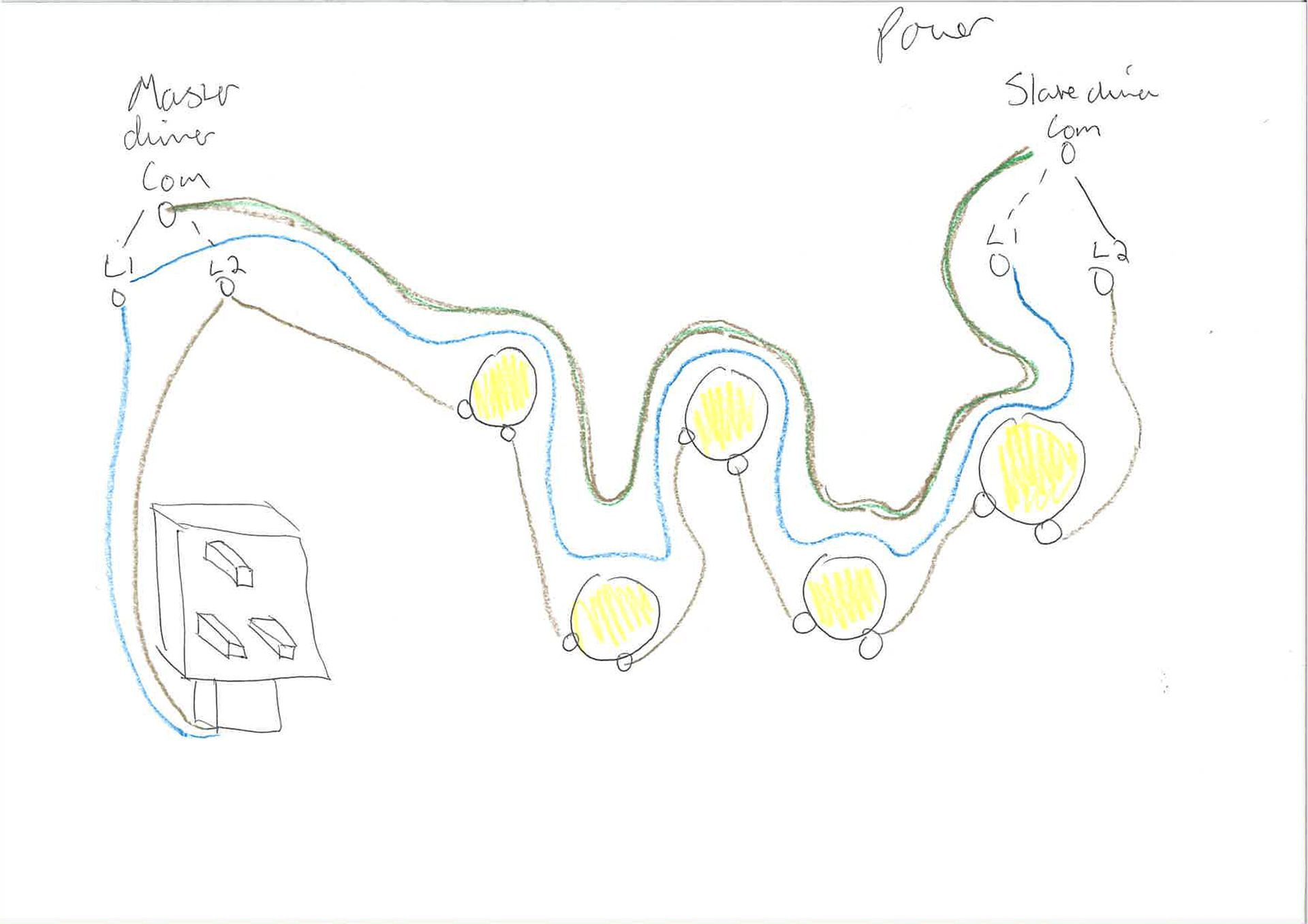
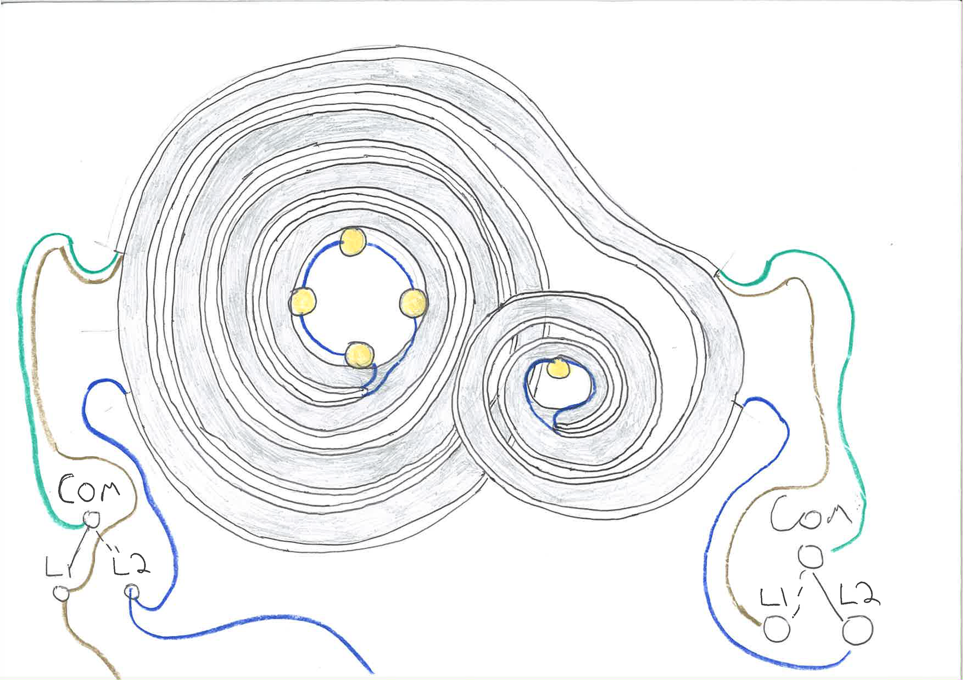
Once again I wanted to reduce the wiring in the light. I realized that I could reduce the wire/cable by placing the bulbs in between the coms on each switch
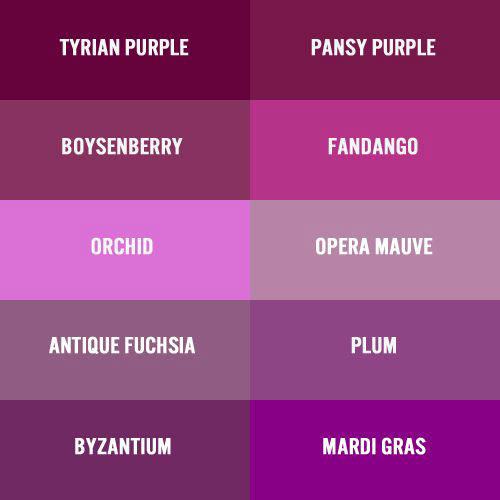
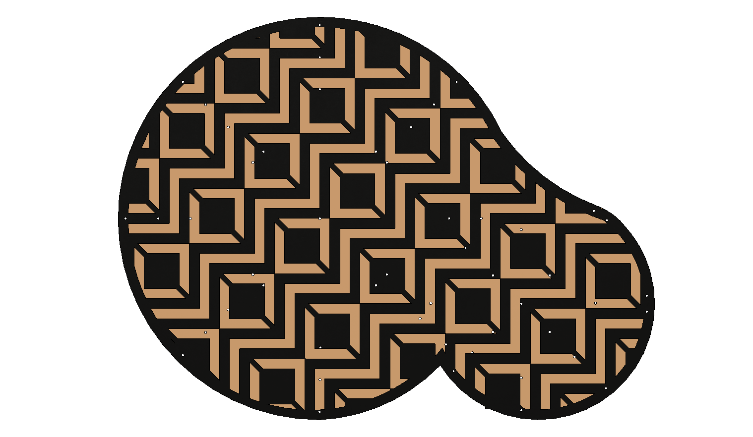
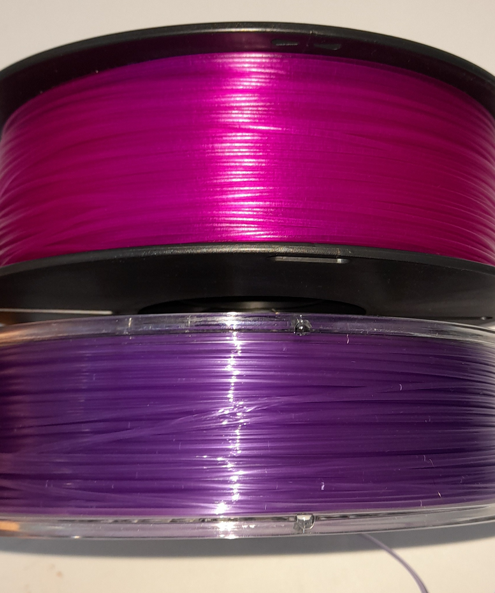
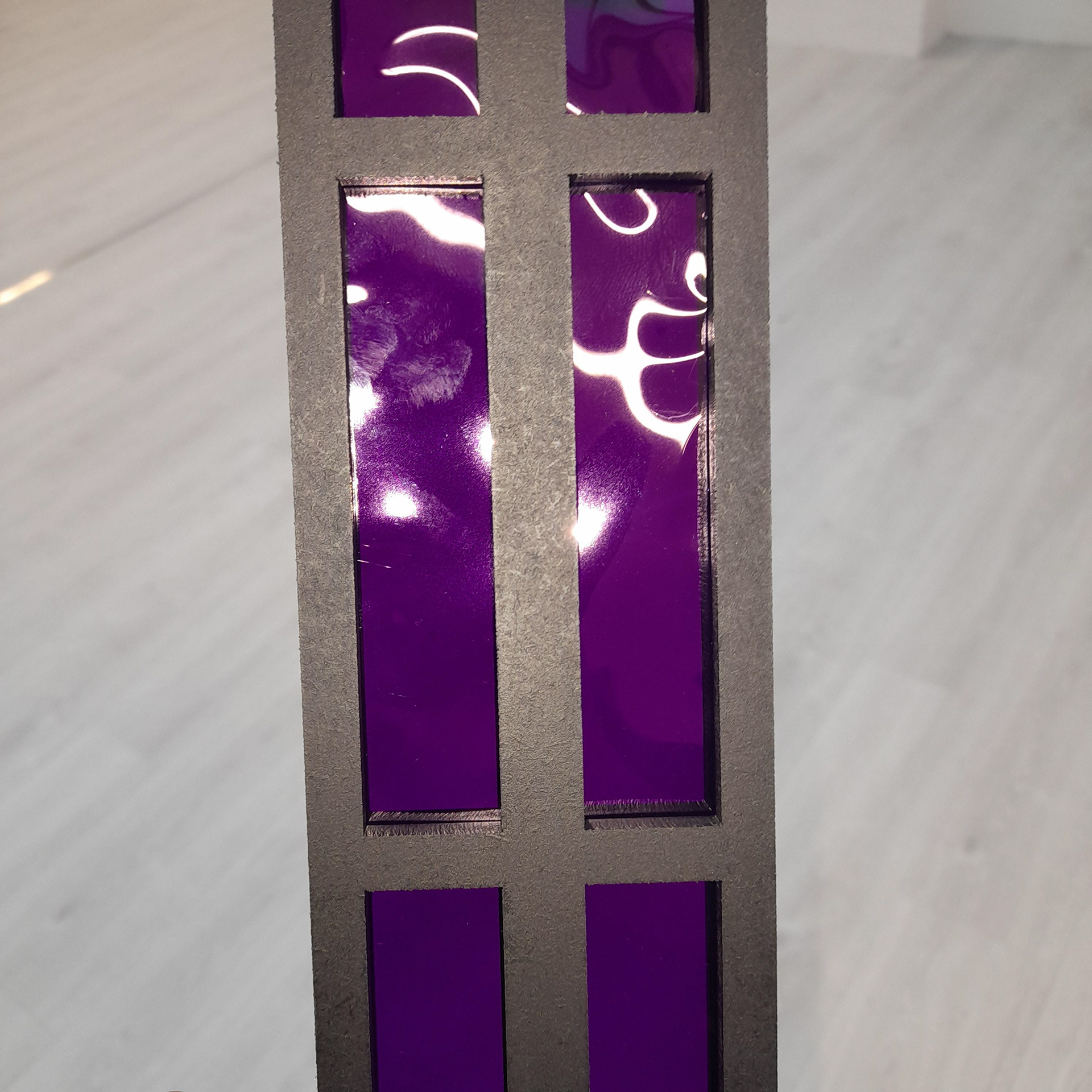
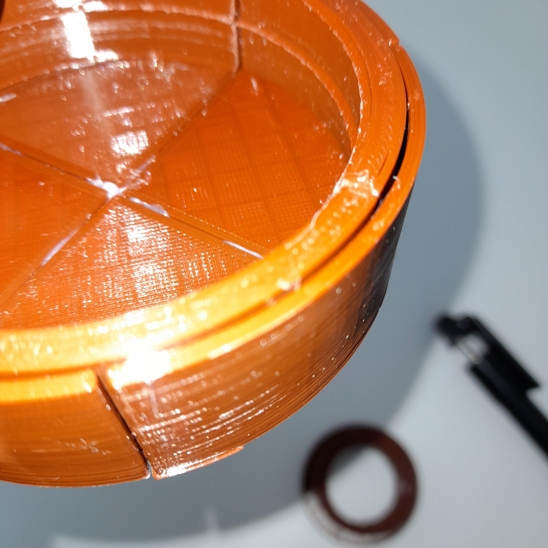
The shades on the light are based on a Tyrian purple (slightly transparent), yet it is difficult to acquire such in 3d filaments. That's why I came up with the idea of using similar colours and overlapping them.
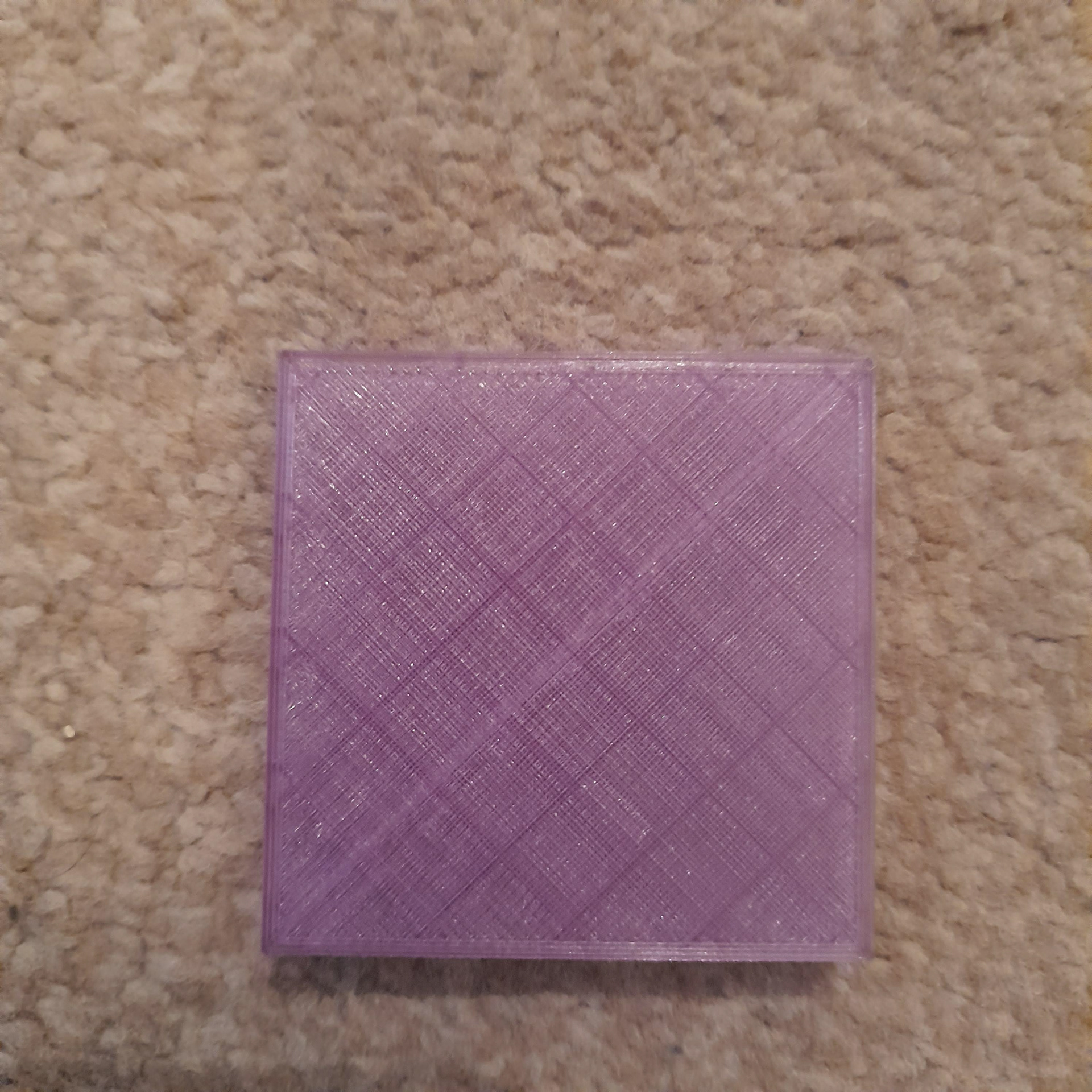
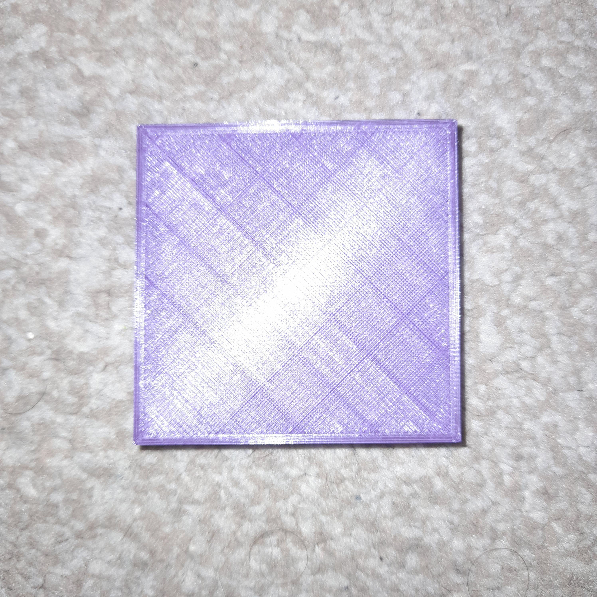
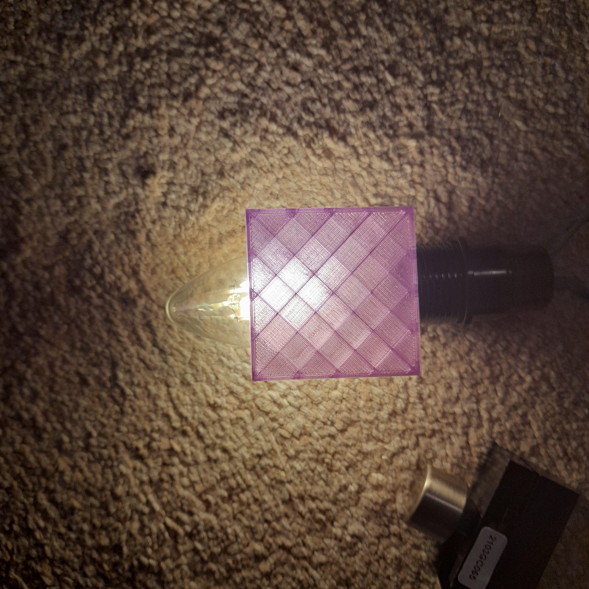
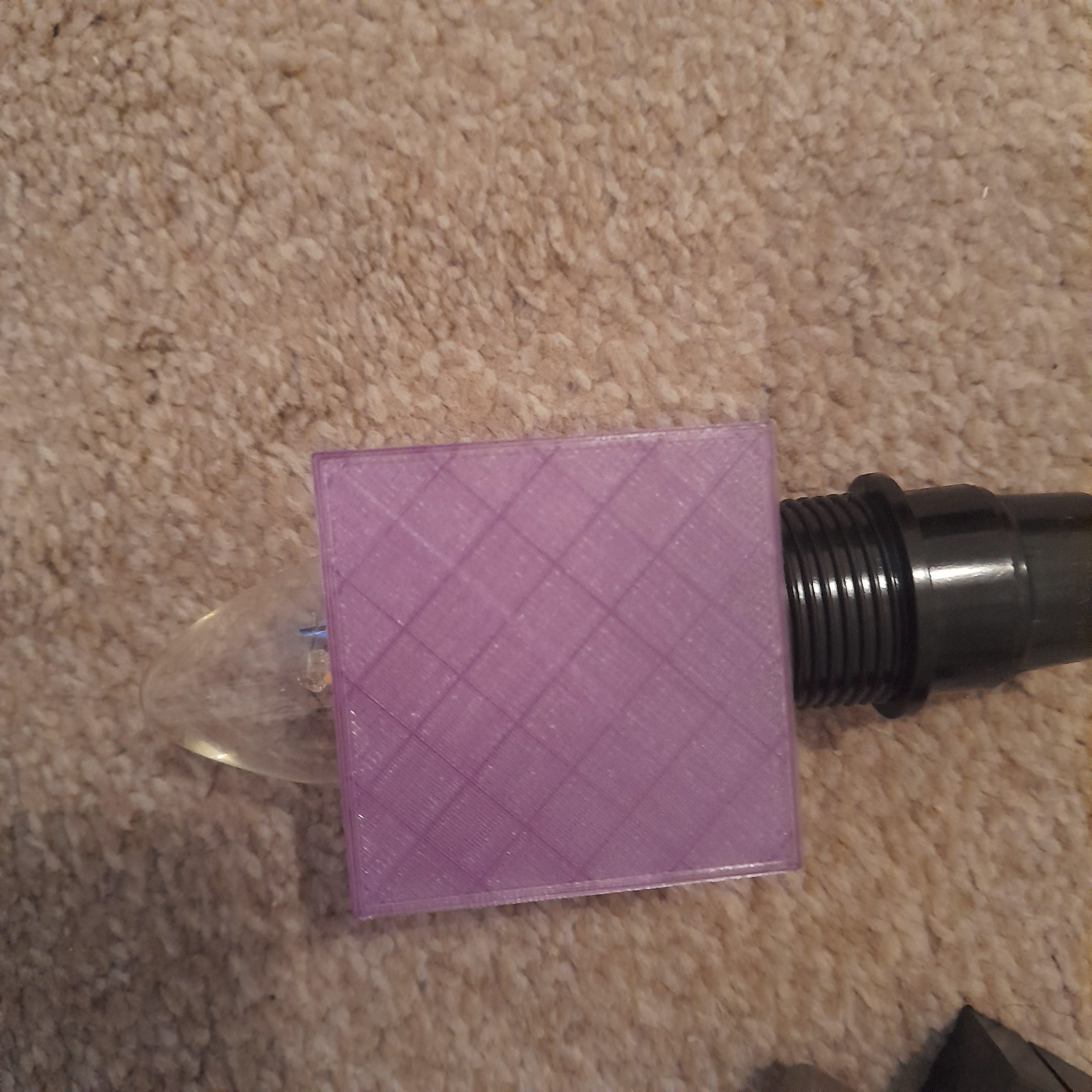
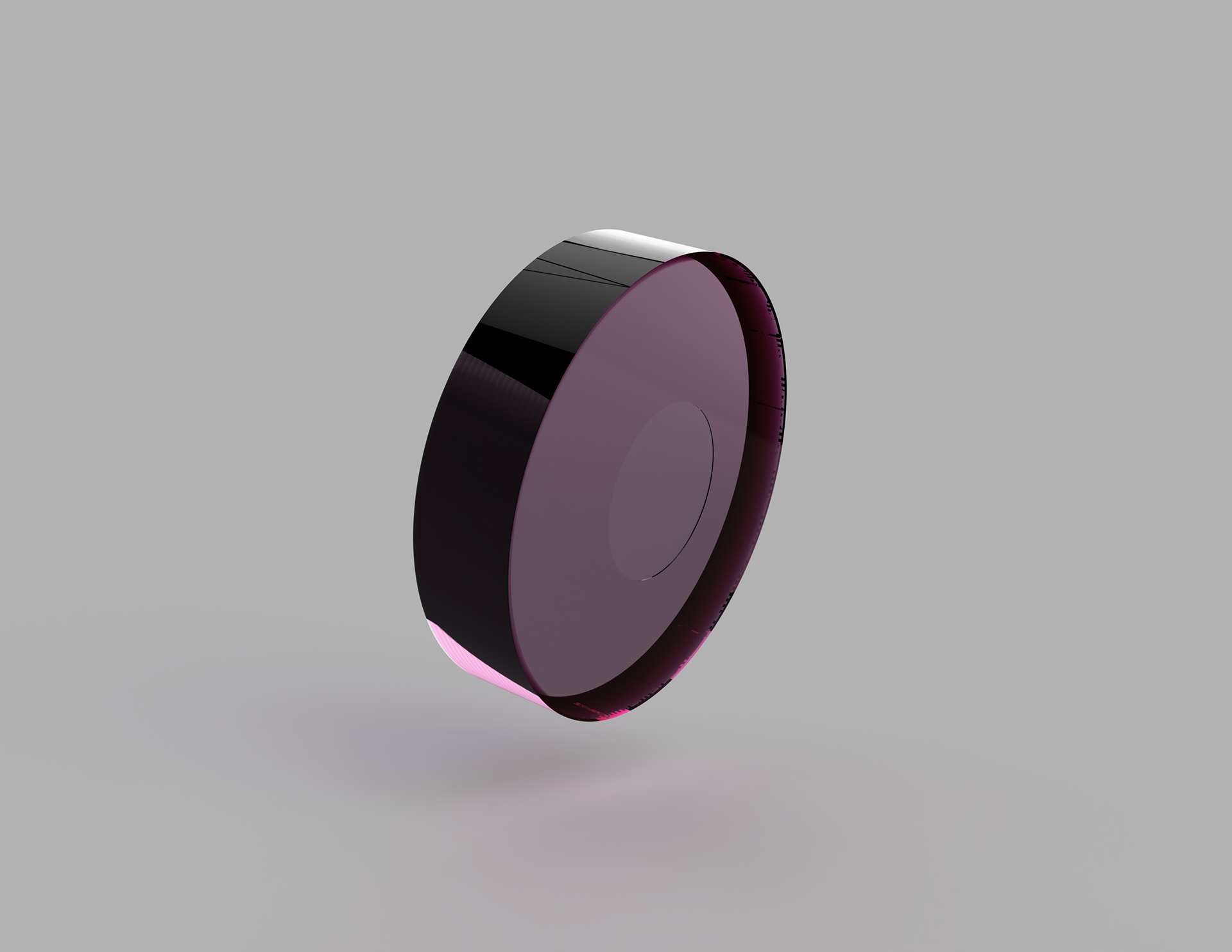
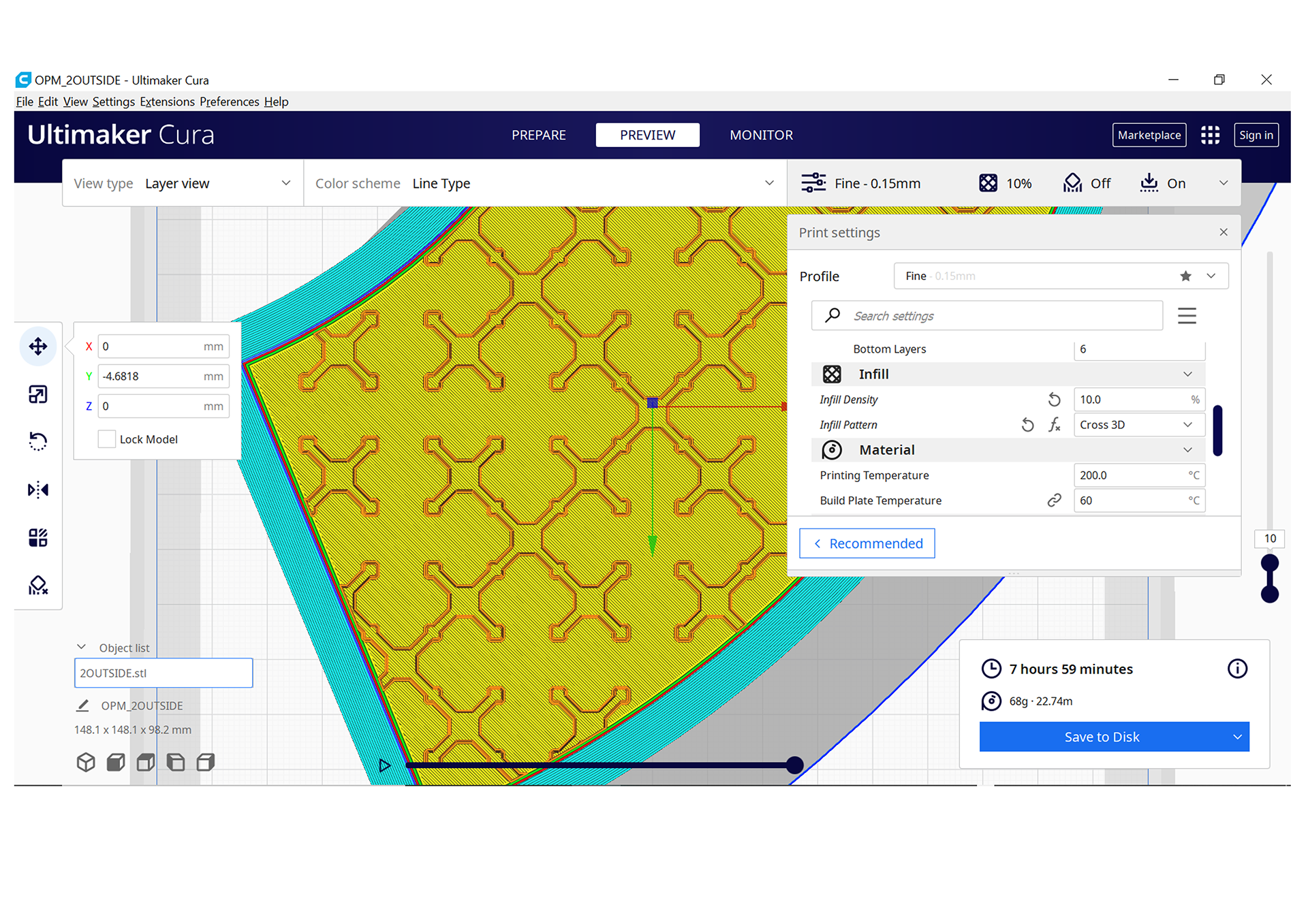
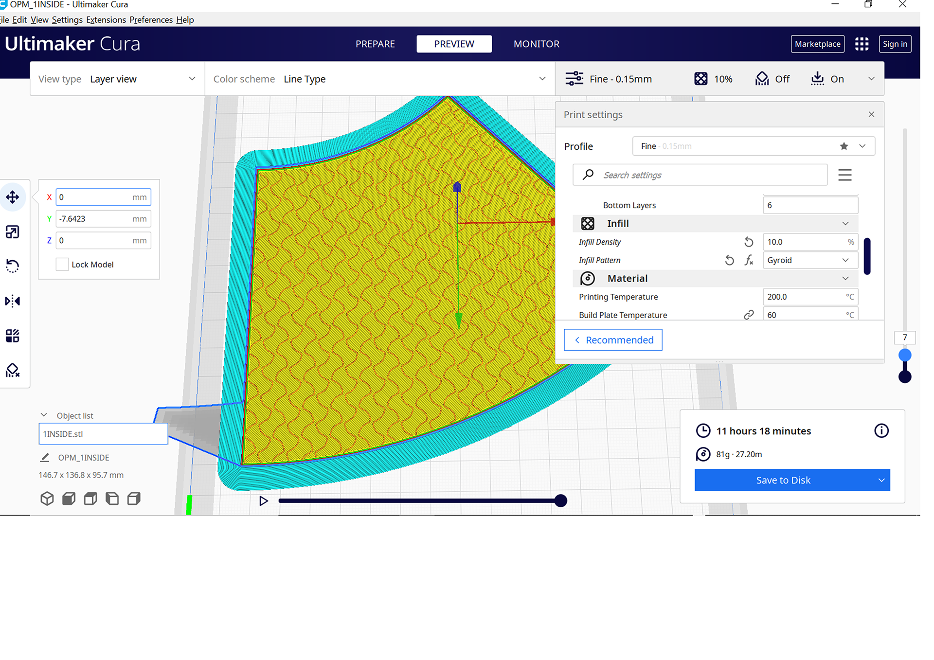
Since they are going to overlap, I decided to try out different infills. I selected two types. The first is a cross pattern which is referring to the croiser word in the section. The second is this wave pattern which reminded me of the term concertina locomotion.
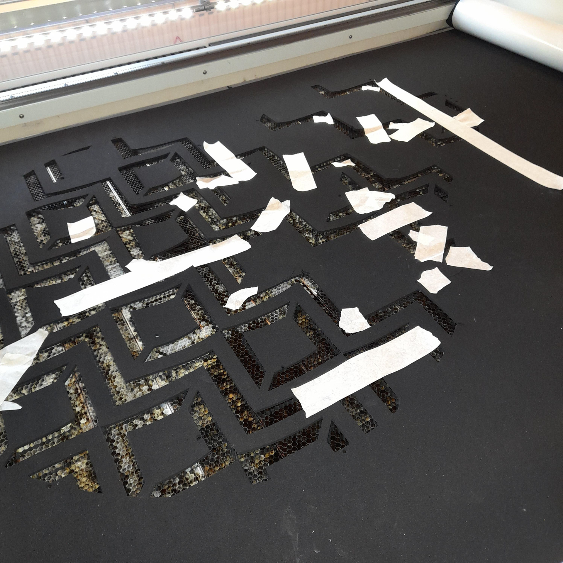
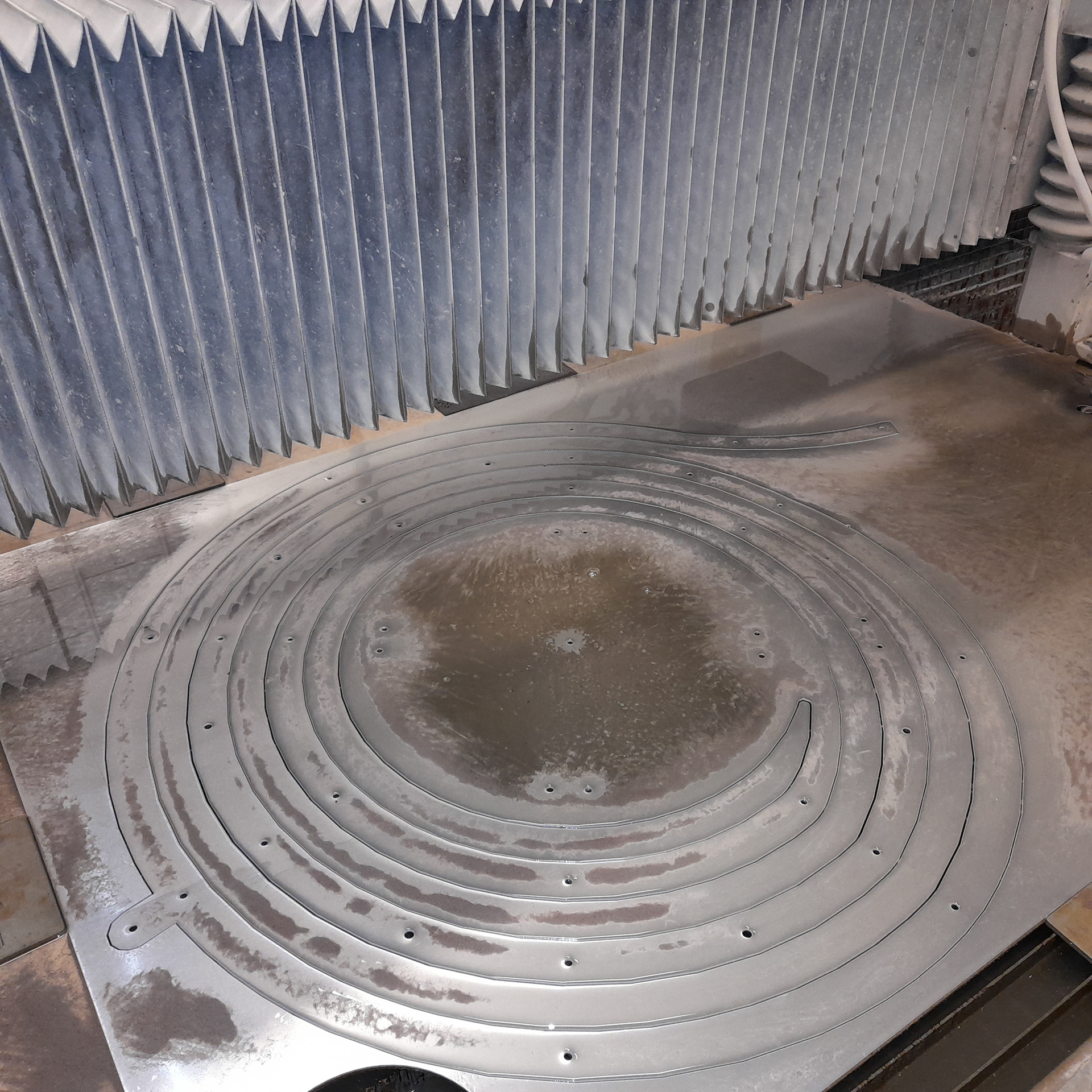
There was a slight issue when laser cutting the rubber. It would curl upwards and tear in some places. However, since the rubber is on the inside of the light I decide to use it anyway since this is a model of the idea and you wouldn't necessarily notice it.
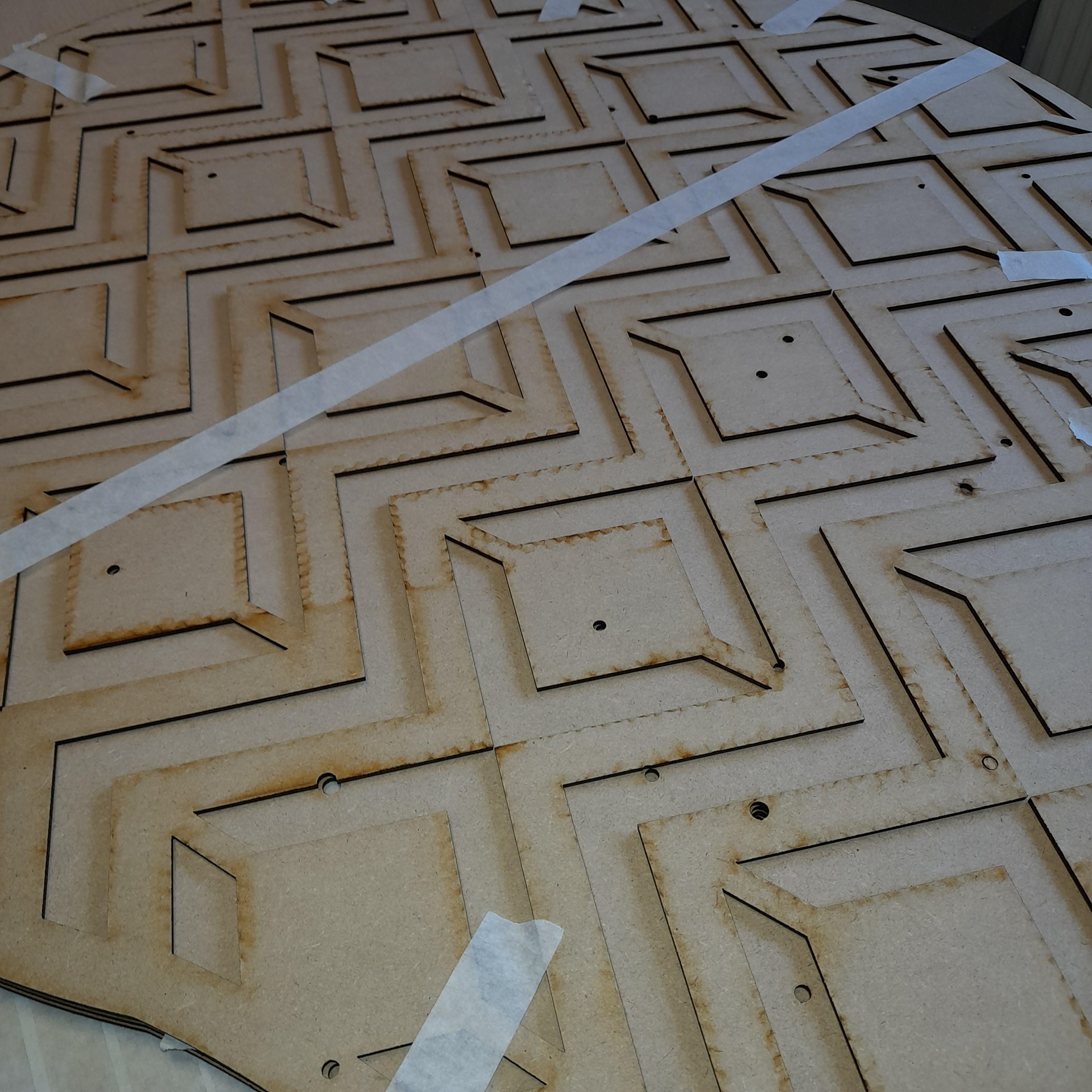
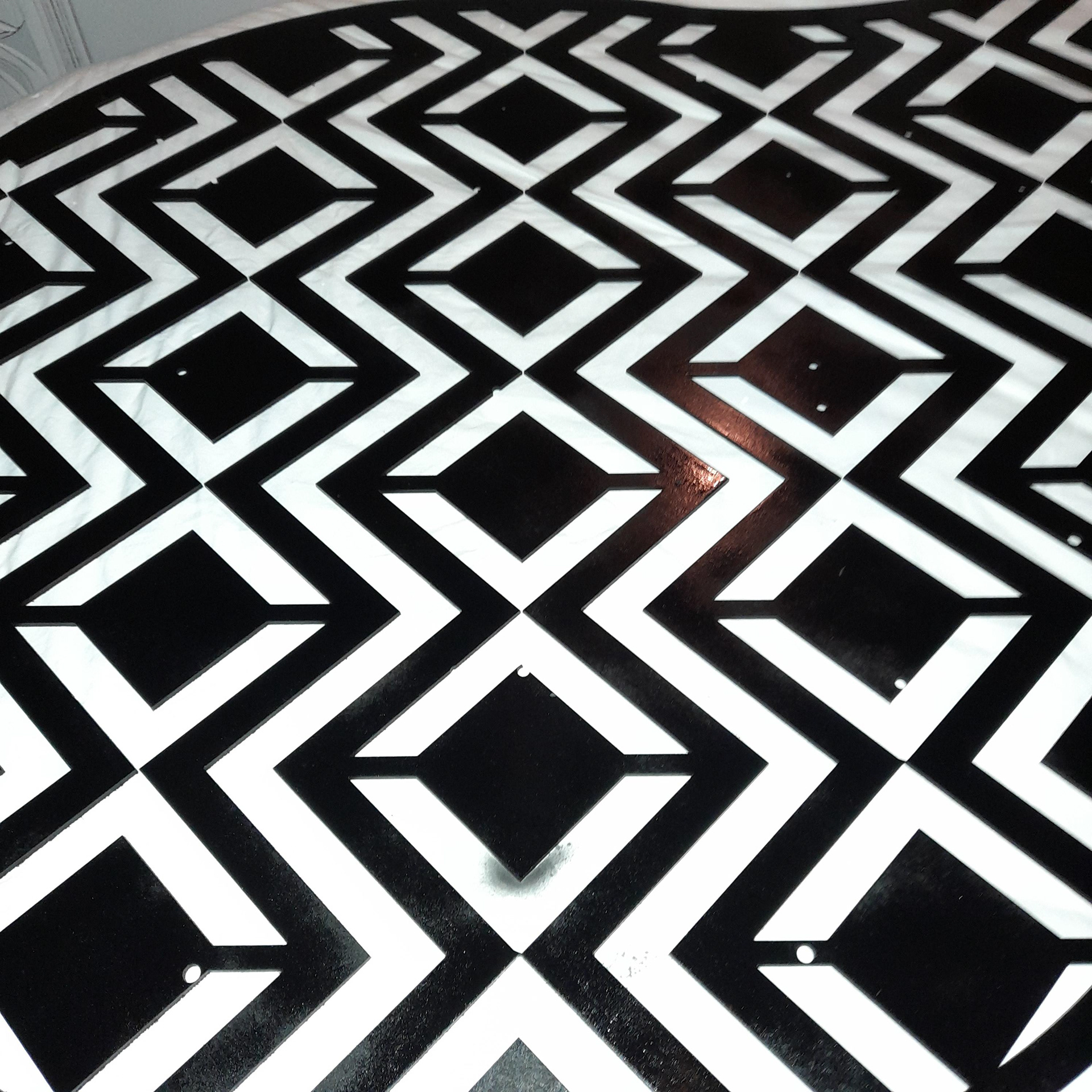
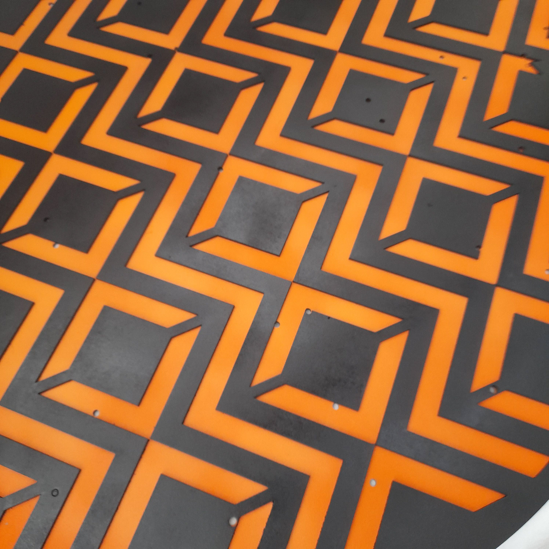
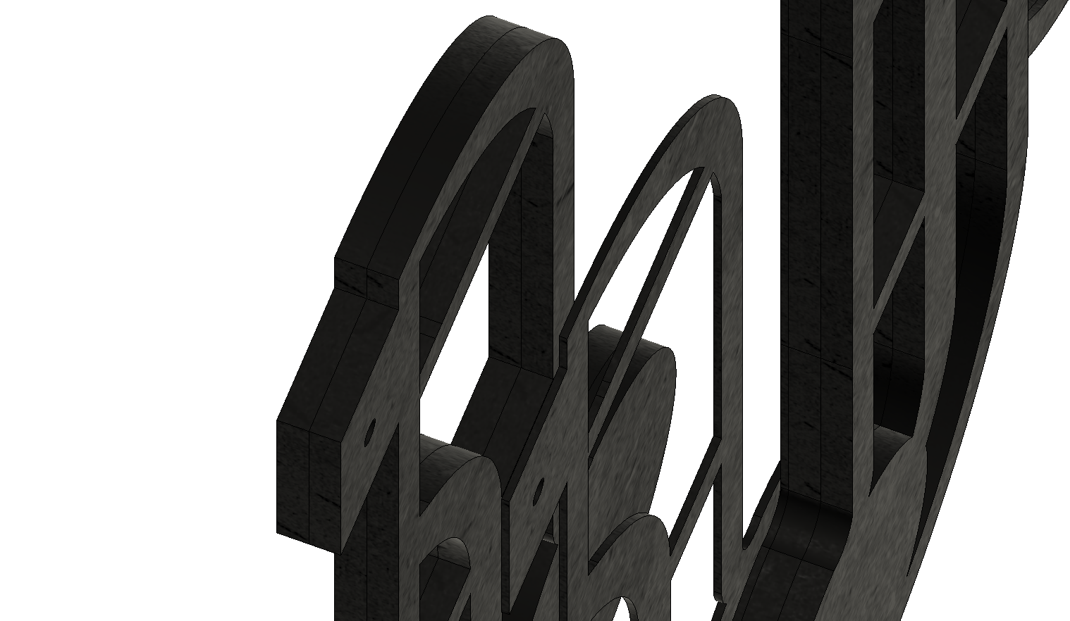
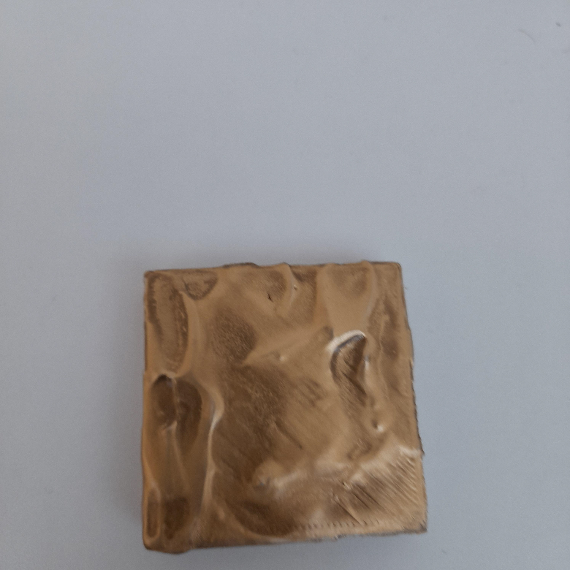
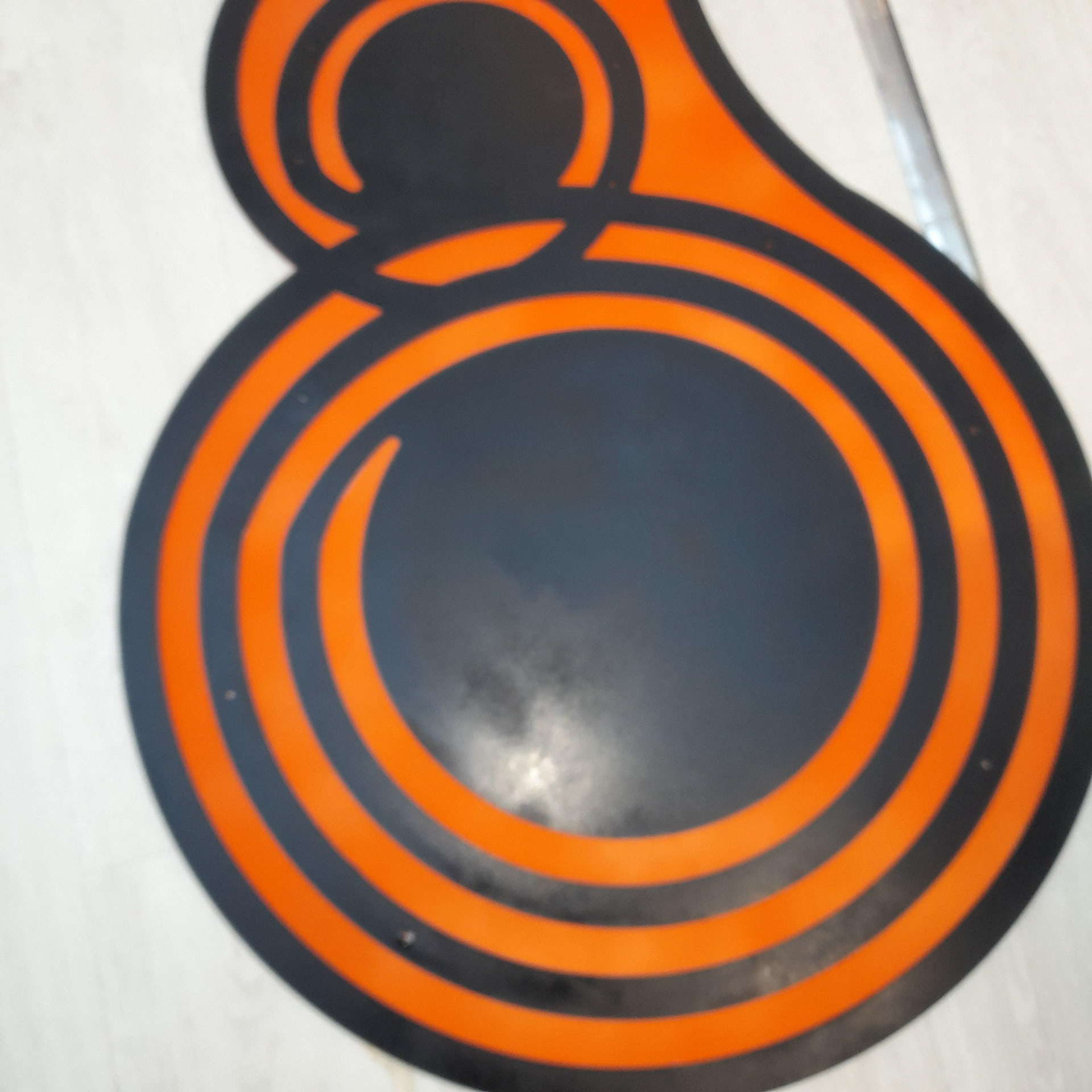
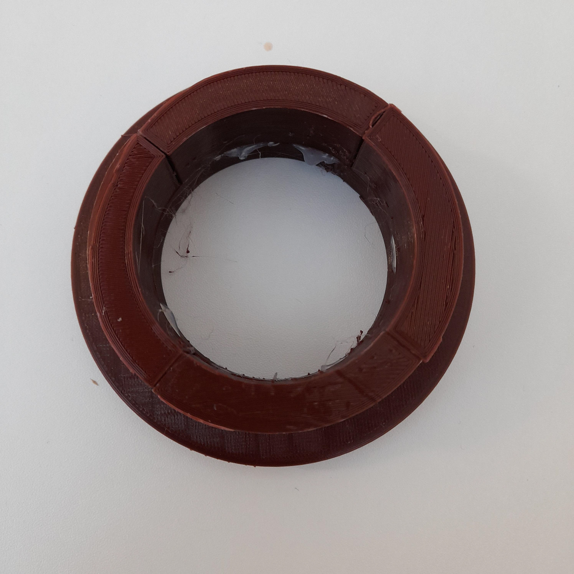
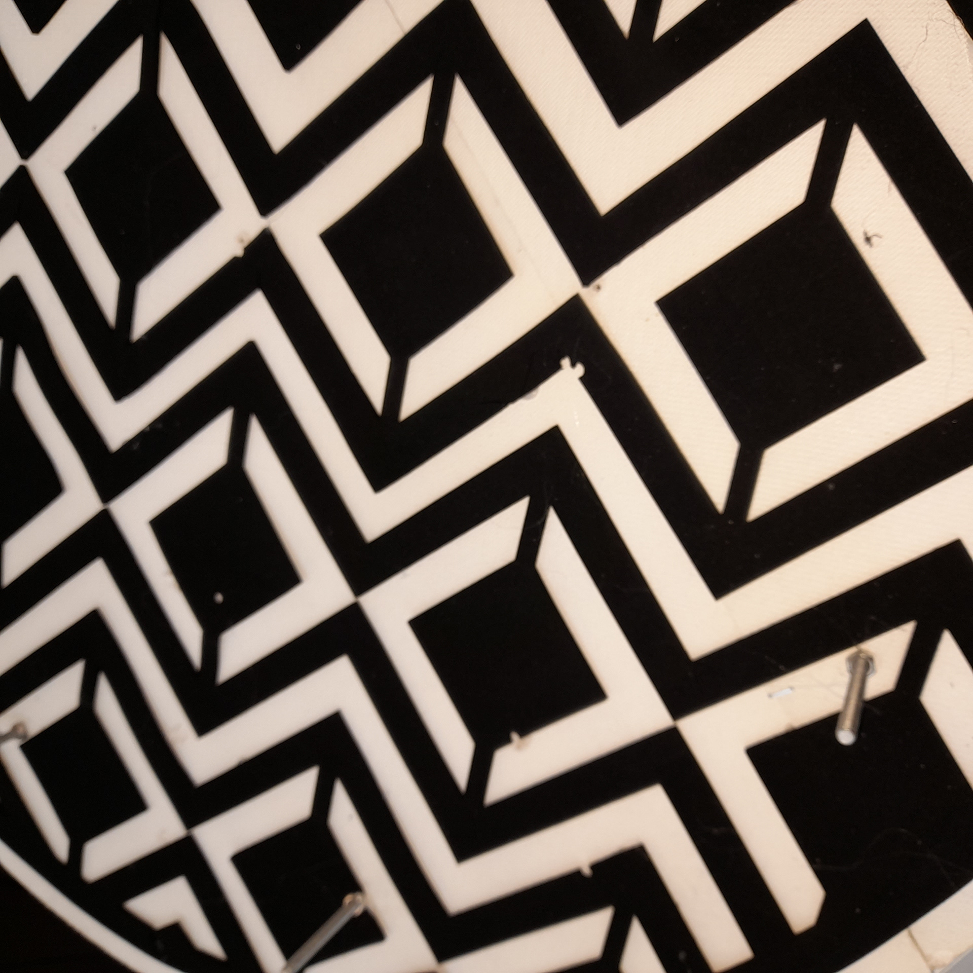
Earlier on I mentioned how I used a meander pattern as an influence. Therefore I tried to replicate this effect on the model. The idea behind it was to create the same visual appearance as what you would find on a greek pot or vase. As in the orange clay surface.
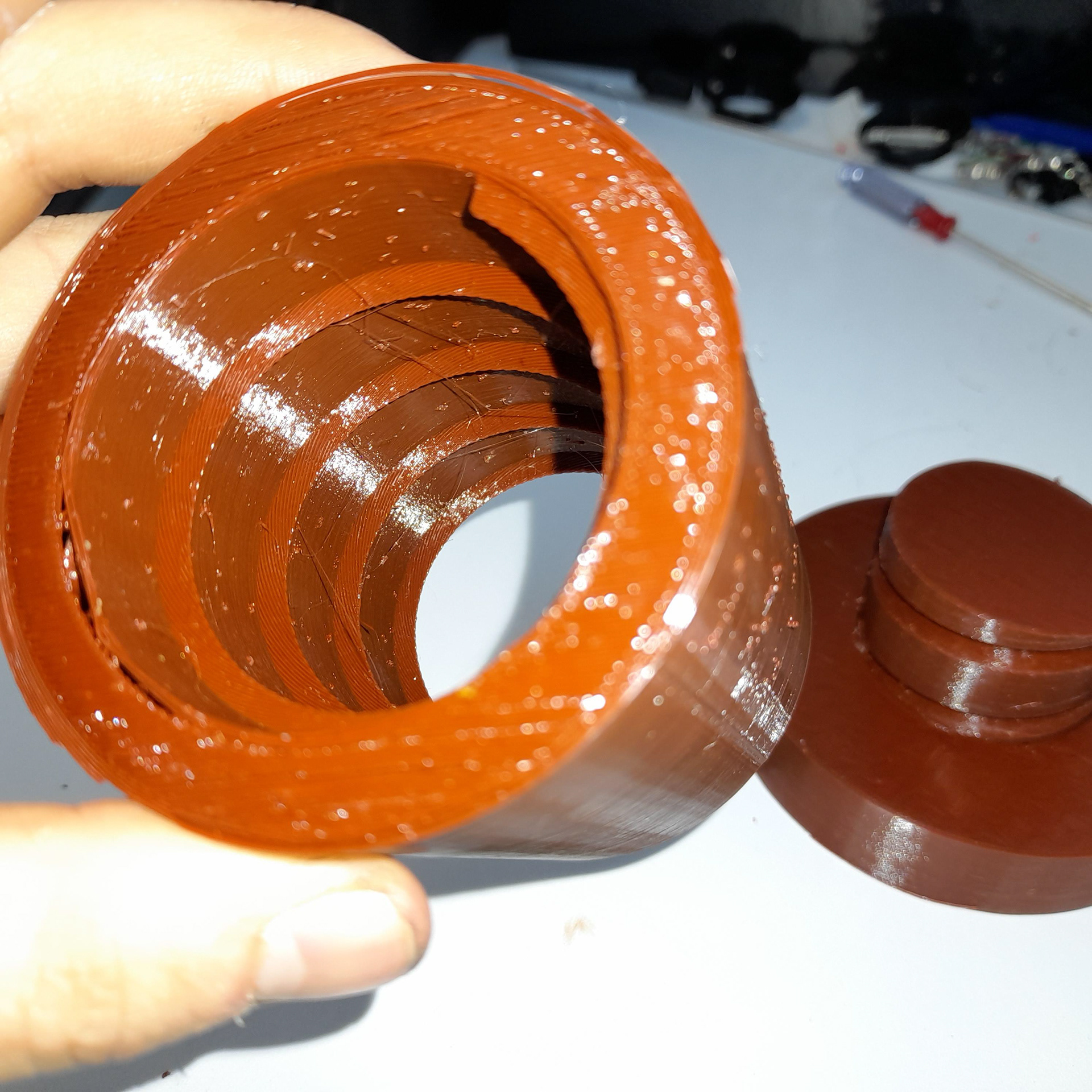
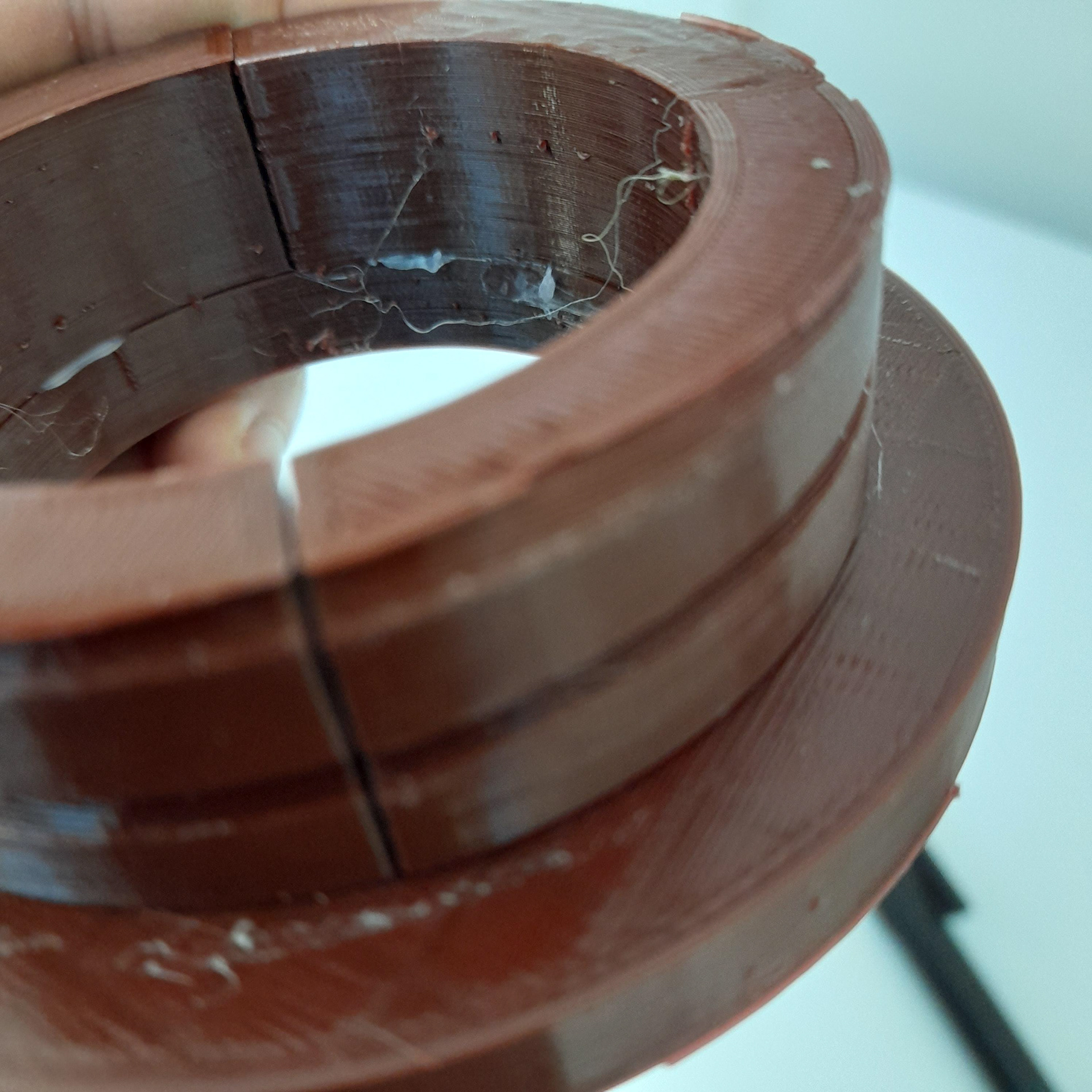
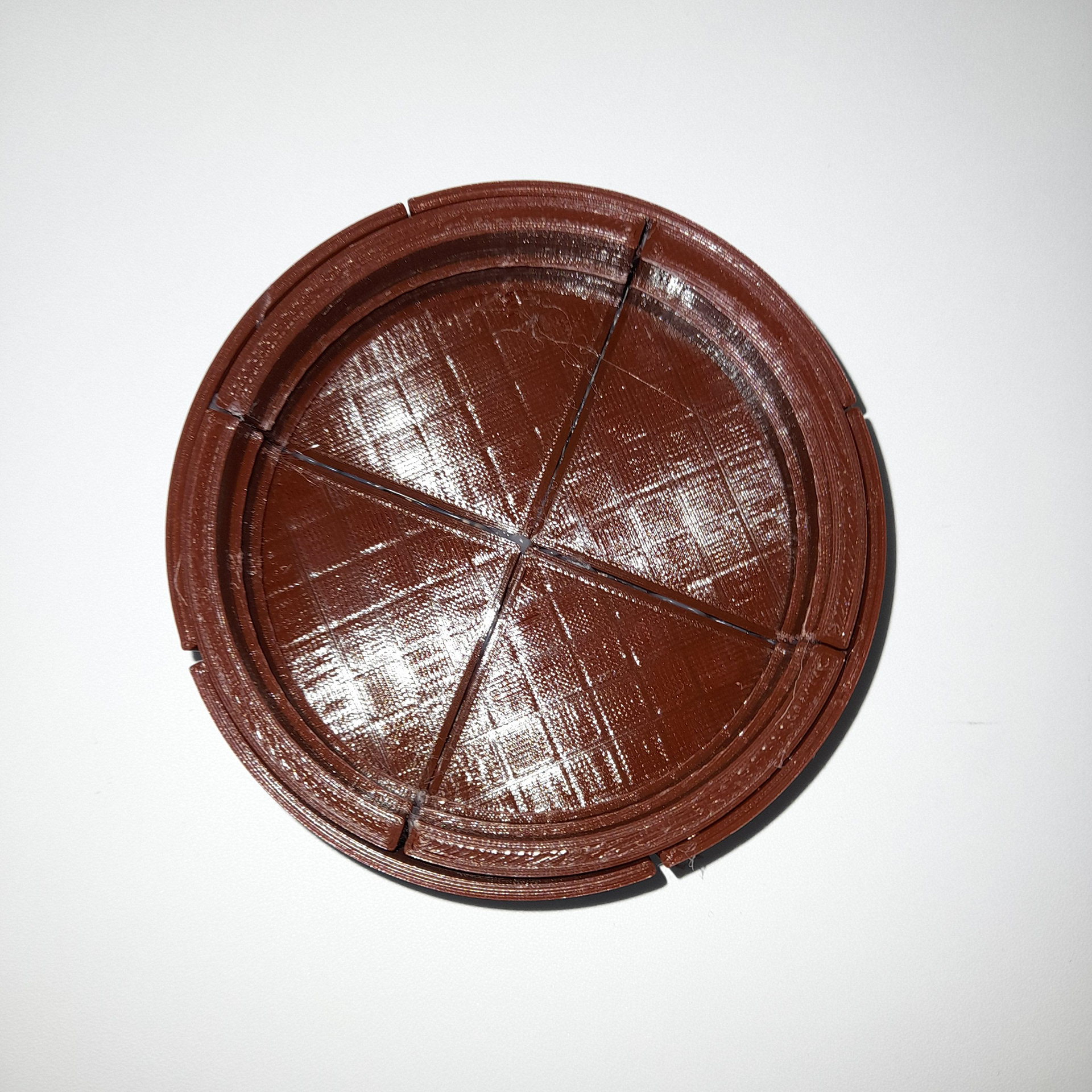
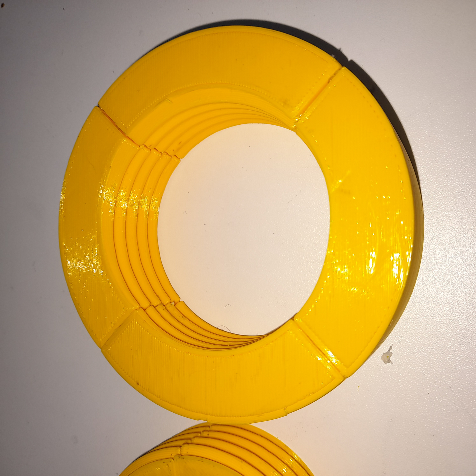
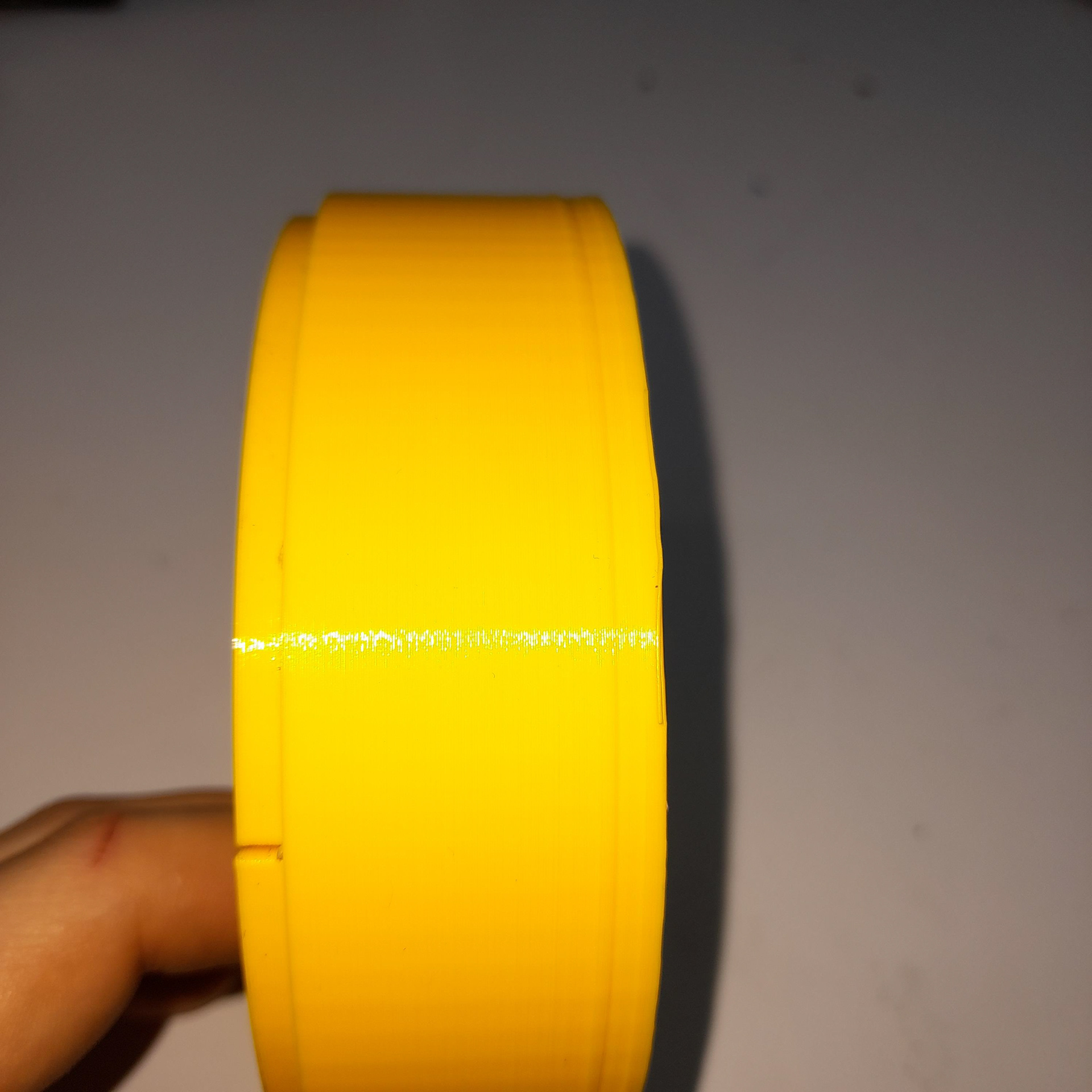
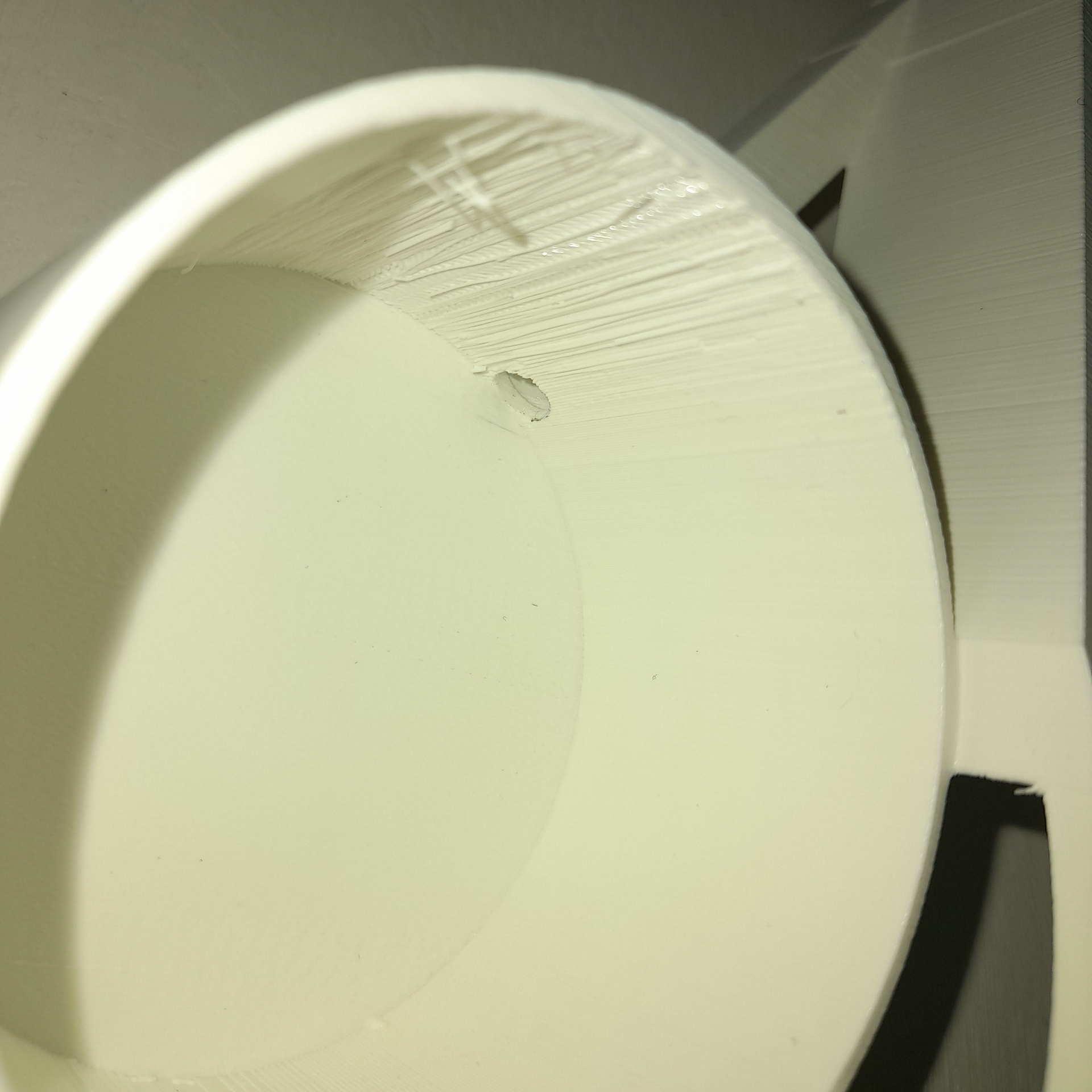
The shades are large on the light. Fusion 360 threads are not suitable for pieces that are large. Therefore I had to make my own using the coil feature. This meant I had to do more trial runs to figure out the minimum and maximum measurements.
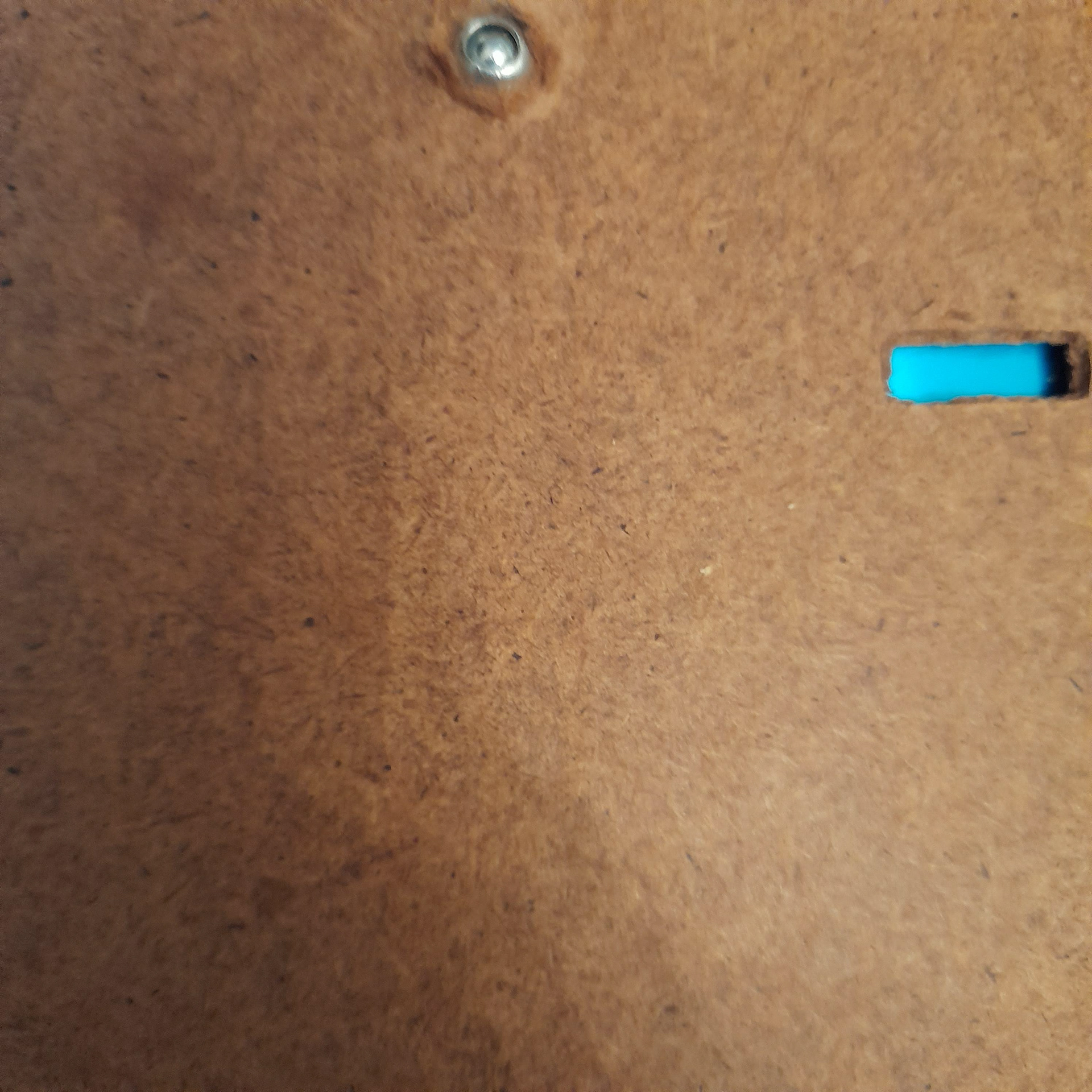
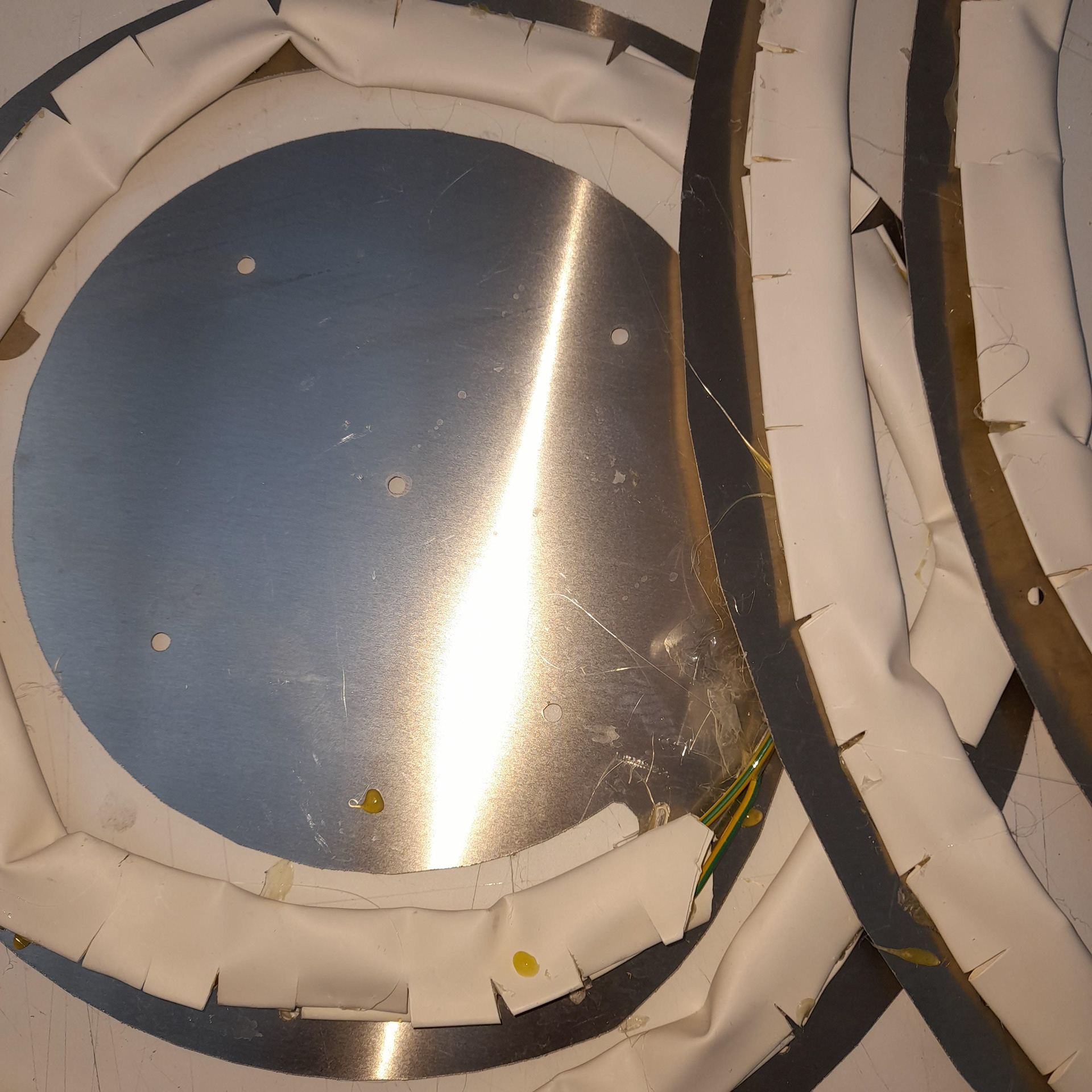
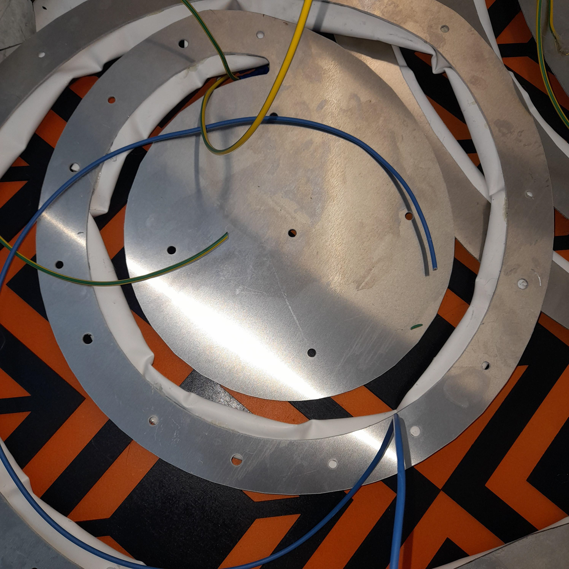
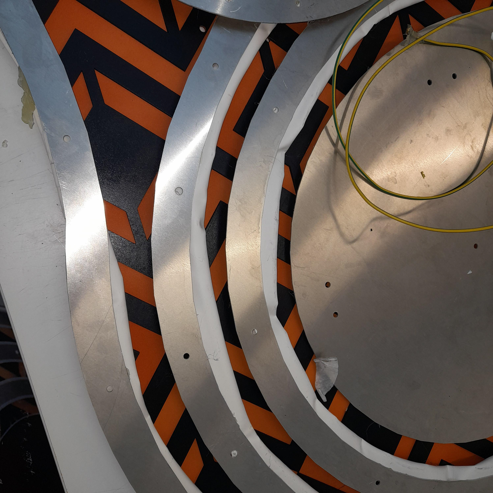
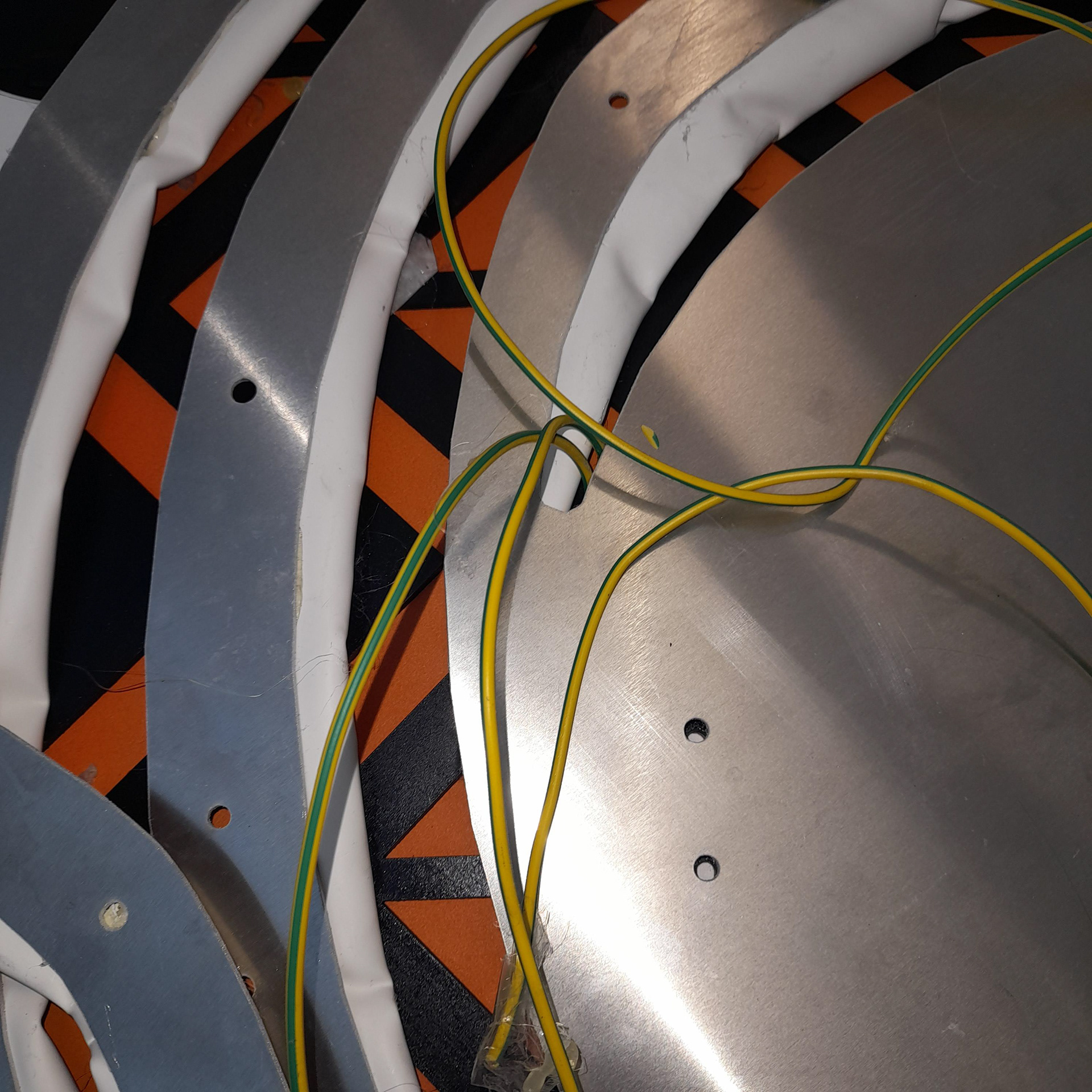
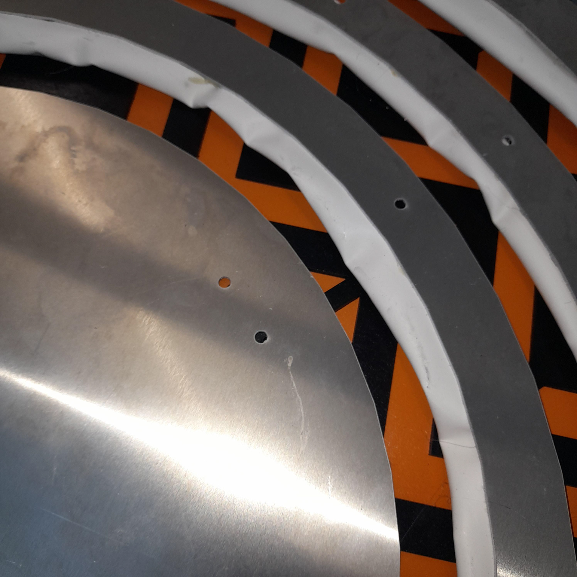
There was an issue with the heat shrink under the metal. When riveting the metal and wood boards together with the heat shrink in between, the vibration was causing the heat shrink to come loose in some areas. This led to the glue bond breaking. So instead of struggling away, I striped the heat shrink off completely. Since I still wanted to include a white feature I placed a slightly larger cut out of the whorl behind. The wiring will now be placed between the original board and the new white one.
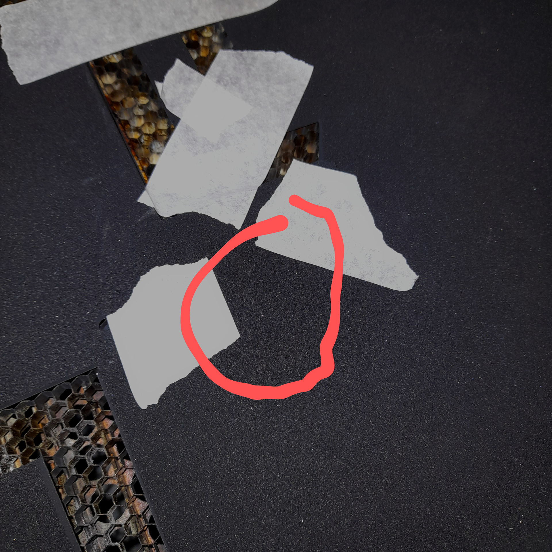
The rubber that was ripped is not that noticeable when glued down
the wiring of the light took a few attempts. There were faulty bulbs, the cable had been snaped and some bad crimping. That being said I did realize that it would be better suited if was wired in a parallel circuit rather than a series and I also decided to scrap all the initial cables and instead soldered new ones together. Hence the video above shows some of the initial issues.